Acousto-optic Modulator for High-power Pulsed Fiber Laser 807
Acousto-optic Modulator for High-power Pulsed Fiber Laser
Abstract:
The present invention relates to an acousto-optic modulator for high-power pulsed fiber lasers, including an input pigtail, a collimating lens, an acousto-optic device, a focusing lens, and an output pigtail. The input pigtail is placed at 3.7° with the horizontal plane, and the output tail The fiber and the horizontal plane are placed at 0° or 3.7°, the input pigtail and collimating lens are installed together to form an input fiber collimator, and the output pigtail and focusing lens are installed together to form an output fiber collimator, and then the input, The output fiber collimator and the acousto-optic device are assembled as a whole; a narrowband filter can be placed between the acousto-optic device and the output fiber collimator, and the input fiber collimator and output fiber collimator can be combined into one Fiber collimator, add a narrow band high reflector. The invention effectively improves the mechanical stability of the laser system, can effectively suppress the nonlinear effect in the doped fiber, and realizes high-power, narrow-spectrum pulsed laser output by coating different components.
Background technology
Q-switched double-clad fiber lasers have many advantages such as low price, compact structure, high efficiency, narrow line width, tunable wavelength, etc., in many fields such as remote sensing, ranging, medical, military, industrial processing, nonlinear optical applications, etc. Widely used.
At present, the commonly used method to obtain high-power pulses through double-clad fiber is that the main oscillator provides a “seed” pulse, and then injects it into the double-clad fiber amplification (M0PA) to obtain it. The seed oscillator (M0) often uses a mode-locked laser or Traditional Q-switched solid-state lasers [see Prior Art: CLE02002, CThX3, 591]. A simpler method is to insert a Q-switched device directly into the double-clad fiber laser cavity to obtain high peak power and high energy lasers. Pulse [see Prior Art: CLE02003,626]. Although the above two methods can obtain high-power pulsed laser output, it is not easy to realize the full fiber laser of the laser.
In order to realize the full fiberization of the fiber laser, one method is to use a modulated semiconductor laser as the M0 in the M0PA structure, that is, a multi-stage fiber amplification structure [see Prior Art: Opt. Lett., 30 (24), 2005, P3299] . The disadvantage of this method is that the output power of the seed source is small, and multi-stage amplification is required to achieve the required power, and an optical isolator is required before each stage of amplification, which easily produces nonlinear effects in the fiber, which limits its output power. The further increase, and the cost is higher. Another method is to insert a pigtailed Q-switched device into the double-clad fiber laser cavity. This method also realizes the full fiberization of the laser, making the laser more compact, but it is easy to carry at high power. The new problem of self-excited oscillation in the cavity also limits the further increase of laser power.
The purpose of the present invention is to overcome the above-mentioned problems in the prior art and provide an acousto-optic modulator for high-power pulsed fiber lasers. The acousto-optic modulator of the present invention has pigtail input and output, which can easily realize the All fiber optic. Corresponding treatment of the end face of the pigtail can suppress the self-excited oscillation in the doped fiber, so as to achieve high-power pulsed laser output, and achieve narrow-spectrum laser output by coating different components.
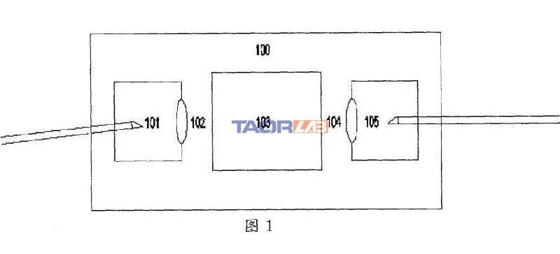
The structure of the acousto-optic modulator for high-power pulsed fiber lasers of the present invention is shown in Figure 1, Figure 2 and Figure 3.
Acousto-optic modulator for high-power pulsed light, including input pigtail 101, collimating lens 102, acousto-optic device 103, focusing lens 104 and output pigtail 105. Input pigtail 101 is placed at 3.7° with the horizontal plane, and output The pigtail 105 is placed at 0° to the horizontal plane, the input pigtail 101 and the collimating lens 102 are installed together to form an input fiber collimator, and the output pigtail 105 and focusing lens 104 are installed together to form an output fiber collimator, and then the input The fiber collimator, the output fiber collimator, and the acousto-optic device 103 are assembled as a whole 100. The input pigtail 101 and the output pigtail 105 are fused with fiber end caps and each ground into an oblique 8° plane, and A broadband antireflection film is plated on the oblique 8° plane of the input pigtail 101, and a narrowband transmission film is plated on the oblique 8° plane of the output pigtail 105. As shown in Figure 1.
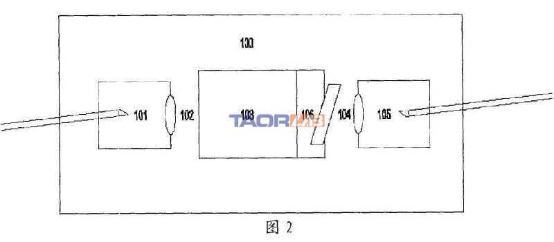
The acousto-optic modulator of another structure of the present invention is shown in Fig. 2. The input pigtail 101 is placed at 3.7° with the horizontal plane. The input pigtail 101 and the collimating lens 102 are installed together to form the input fiber collimator. The ends of the fiber 101 are fused with fiber end caps and each ground into an oblique 8° plane, and a broadband anti-reflection coating is plated on the oblique 8° plane. The output fiber formed by the acousto-optic device 103, the output pigtail 105 and the focusing lens 104 is collimated A narrow-band filter 106 is placed between the devices, and the output pigtail 105 is placed at 3.7° from the horizontal plane. A broadband anti-reflection coating is plated on the oblique 8° plane of the output pigtail 105. The acousto-optic device 103 and the narrow-band filter 106 are installed together. , And the narrow-band filter 106 and the first-order diffraction direction of the acousto-optic device 103 are placed at a corresponding angle, so that the narrow-band filter 106 has the maximum transmittance to the set wavelength, and cannot reflect other wavelengths of light back to the acousto-optic The device 103 enters the input fiber collimator, and then the input fiber collimator, the output fiber collimator and the acousto-optic device 103 and the narrowband filter 106 are assembled as a whole 100.
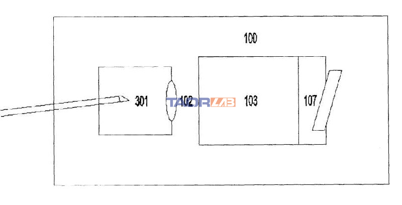
Another structure of the acousto-optic modulator of the present invention is shown in Figure 3. The input pigtail and output pigtail are combined into a pigtail 301, the focusing lens 104 is removed, and a narrow-band high reflector 107 is added. The pigtail 301 is connected to the horizontal plane. Place it at 3.7° and install it with the collimating lens 102 to form a fiber collimator. The end of the pigtail 301 is fused with a fiber end cap and ground to an 8° bevel, and the bevel is plated with a broadband antireflection coating, acousto-optic device 103 And the narrow-band high-reflective mirror 107 are installed together, and the narrow-band high-reflective mirror 107 is perpendicular to the first-order diffracted light through the acousto-optic device 103, and then the two parts are assembled into a whole 100.
The three acousto-optic modulators of the present invention are free of internal adjustment, which greatly improves the mechanical stability of the entire system.
The 1064±0.5nm anti-reflection coating is plated on the 8-degree oblique surface of the output pigtail 105. Only for Yb-doped fiber lasers, the anti-reflection coating of the corresponding wavelength can be selected according to the working wavelength of the doped fiber. The anti-reflection coating is highly transparent to the 1064+0.5nm laser, ensuring that the laser of this wavelength forms an oscillating output in the cavity, and the light of the other wavelengths obliquely has a large reflection loss, thereby narrowing the width of the laser output spectrum.
The narrow-band filter 106 is placed at an angle with the acousto-optic modulator 103, and the surface is coated with a narrow-band transmission film. The narrow-band transmission film of the corresponding wavelength can be selected according to the working wavelength of the gain fiber. For example, the Yb-doped fiber laser is coated with 1064± The 0.5nm narrow-band transmission film ensures that the laser with the set wavelength will form an oscillating output in the cavity, while obliquely facing the light of the other wavelengths has a large reflection loss, thereby narrowing the width of the laser output spectrum.
The surface of the narrow-band high reflection mirror 107 is coated with a narrow-band high-reflection film. The narrow-band high-reflection film of the corresponding wavelength can be selected according to the working wavelength of the gain fiber. For example, for a Yb-doped fiber laser, a 1064+0.5nm narrow-band high-reflection film is coated , Placed perpendicular to the first-order diffraction direction of the acousto-optic device, to ensure that the laser of the set wavelength forms an oscillating output in the cavity, and the light of the other wavelengths has a large transmission loss, thereby narrowing the width of the laser output spectrum.
The invention is an acousto-optic modulator with pigtail input and output, easy to realize all-fiber fiber laser, which effectively improves the mechanical stability of the laser system, can effectively suppress the nonlinear effect in the doped fiber, and can be used in different components The method of coating film to achieve high-power, narrow-spectrum pulsed laser output.
Specific implementation
As shown in Figure 4, the pigtailed 915nm pumped semiconductor laser 401 is fused to the total reflection fiber grating 402, the total reflection fiber grating is fused to the gain fiber 403, the gain fiber is fused to the input pigtail 404, and the input pigtail is fused to the fiber end The cap is ground into an 8° inclined surface, then a broadband antireflection coating is plated, and it is placed at 3.7° from the horizontal. The laser generated by the gain fiber passes through the input pigtail 404 and the collimating lens 405 to form a collimated beam into the acousto-optic The device 406 generates Bragg diffraction, and the diffracted first-order light is coupled into the pigtail 408 through the focusing lens 407. The output pigtail 408 is fused with a fiber end cap, ground into an 8° bevel, coated with a narrow-band anti-reflection coating, and placed at 0° from the horizontal plane. In this way, only the narrowband wavelength set in the first-order diffracted light is allowed to enter the output pigtail 408, while reflecting other wavelengths, the reflected other wavelengths will not enter the output pigtail through the acousto-optic device, and the output pigtail 408 and part of the The reflective fiber grating 409 is spliced. In this way, the fiber gratings 402 and 409 form a resonant cavity. Because the output pigtail 408 and the oblique 8° surface are coated with a narrow-band anti-reflection coating, the excitation of other wavelengths is suppressed, so that the pulse fiber laser formed in this way has a narrow linewidth output. No nonlinear wavelengths appear. We use this structure to obtain an average output power of 2W at a frequency of 20kHz, a pulse width of 40ns, and a peak power of 2.5kW. Fig. 5 shows the output spectrum of the acousto-optic modulator using the present invention, and comparing it with the spectrum of the same power level generated by the ordinary acousto-optic modulator, it is obvious that the spectrum is broad and has Raman wavelengths.
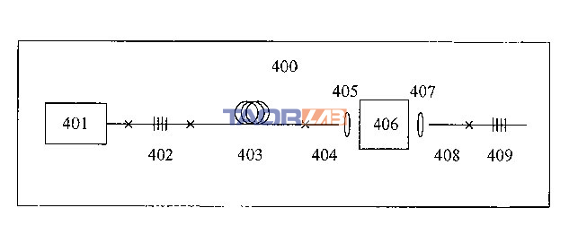
Figure 4: A schematic diagram of a specific embodiment of the present invention.

Figure 5: A graph showing whether to use the output spectrum of the acousto-optic modulator of the present invention and comparing the spectrum with the same power level generated by a common acousto-optic modulator.

oaiuBOcXdbm
AgivWtFc
cyDTShioKtxRgflm
Can you be more specific about the content of your article? After reading it, I still have some doubts. Hope you can help me.
Thanks for sharing. I read many of your blog posts, cool, your blog is very good.
Thank you for your sharing. I am worried that I lack creative ideas. It is your article that makes me full of hope. Thank you. But, I have a question, can you help me? https://www.binance.com/ES_la/register?ref=T7KCZASX
Your article helped me a lot, is there any more related content? Thanks!
Your article helped me a lot, is there any more related content? Thanks!
Your enticle helped me a lot, is there any more related content? Thanks!
I don’t think the title of your article matches the content lol. Just kidding, mainly because I had some doubts after reading the article.
Can you be more specific about the content of your article? After reading it, I still have some doubts. Hope you can help me.
I don’t think the title of your article matches the content lol. Just kidding, mainly because I had some doubts after reading the article.
Keep up the fantastic work! Kalorifer Sobası odun, kömür, pelet gibi yakıtlarla çalışan ve ısıtma işlevi gören bir soba türüdür. Kalorifer Sobası içindeki yakıtın yanmasıyla oluşan ısıyı doğrudan çevresine yayar ve aynı zamanda suyun ısınmasını sağlar.
Thanks for sharing. I read many of your blog posts, cool, your blog is very good. https://accounts.binance.com/ES_la/register-person?ref=T7KCZASX
Your point of view caught my eye and was very interesting. Thanks. I have a question for you.
Thanks for sharing. I read many of your blog posts, cool, your blog is very good.
Thank you for your sharing. I am worried that I lack creative ideas. It is your article that makes me full of hope. Thank you. But, I have a question, can you help me?
Can you be more specific about the content of your article? After reading it, I still have some doubts. Hope you can help me.
Your point of view caught my eye and was very interesting. Thanks. I have a question for you.
Your point of view caught my eye and was very interesting. Thanks. I have a question for you.
Your point of view caught my eye and was very interesting. Thanks. I have a question for you.
I don’t think the title of your article matches the content lol. Just kidding, mainly because I had some doubts after reading the article.
Your point of view caught my eye and was very interesting. Thanks. I have a question for you.
I don’t think the title of your article matches the content lol. Just kidding, mainly because I had some doubts after reading the article.
I don’t think the title of your article matches the content lol. Just kidding, mainly because I had some doubts after reading the article.
Revolutionize your weighing needs with BWER, Iraq’s top provider of weighbridge systems, featuring unparalleled accuracy, durability, and expert installation services.
Your article helped me a lot, is there any more related content? Thanks!
I don’t think the title of your article matches the content lol. Just kidding, mainly because I had some doubts after reading the article.
I don’t think the title of your article matches the content lol. Just kidding, mainly because I had some doubts after reading the article.
Hi there, I discovered your website by way of Google at the same time as searching for a similar matter, your website got here up, it appears to be like great. I have bookmarked it in my google bookmarks.
Appreciate it for this post, I am a big big fan of this website would like to go along updated.
Your point of view caught my eye and was very interesting. Thanks. I have a question for you. https://www.binance.com/en-IN/register?ref=UM6SMJM3
I truly appreciate this post. I¦ve been looking all over for this! Thank goodness I found it on Bing. You have made my day! Thank you again
At BWER Company, we prioritize quality and precision, delivering high-performance weighbridge systems to meet the diverse needs of Iraq’s industries.
Thanks for sharing. I read many of your blog posts, cool, your blog is very good.
Your article helped me a lot, is there any more related content? Thanks!
Great – I should certainly pronounce, impressed with your site. I had no trouble navigating through all tabs as well as related info ended up being truly easy to do to access. I recently found what I hoped for before you know it at all. Reasonably unusual. Is likely to appreciate it for those who add forums or something, website theme . a tones way for your customer to communicate. Excellent task..
Thanks for sharing. I read many of your blog posts, cool, your blog is very good.
Can you be more specific about the content of your article? After reading it, I still have some doubts. Hope you can help me. https://accounts.binance.com/de-CH/register?ref=UM6SMJM3
Your point of view caught my eye and was very interesting. Thanks. I have a question for you. https://accounts.binance.com/register?ref=P9L9FQKY
Your article helped me a lot, is there any more related content? Thanks!
I don’t think the title of your article matches the content lol. Just kidding, mainly because I had some doubts after reading the article.
Can you be more specific about the content of your article? After reading it, I still have some doubts. Hope you can help me.
I don’t think the title of your article matches the content lol. Just kidding, mainly because I had some doubts after reading the article.
Your article helped me a lot, is there any more related content? Thanks! https://www.binance.info/si-LK/register?ref=V2H9AFPY
Thank you for your sharing. I am worried that I lack creative ideas. It is your article that makes me full of hope. Thank you. But, I have a question, can you help me?
I’m still learning from you, while I’m trying to reach my goals. I certainly liked reading all that is posted on your site.Keep the posts coming. I enjoyed it!
Thanks for sharing. I read many of your blog posts, cool, your blog is very good.
Can you be more specific about the content of your article? After reading it, I still have some doubts. Hope you can help me.
Thank you for your sharing. I am worried that I lack creative ideas. It is your article that makes me full of hope. Thank you. But, I have a question, can you help me?
I love it when people come together and share opinions, great blog, keep it up.
Thanks for sharing. I read many of your blog posts, cool, your blog is very good.
Your point of view caught my eye and was very interesting. Thanks. I have a question for you.
I don’t think the title of your article matches the content lol. Just kidding, mainly because I had some doubts after reading the article.
Thanks for another informative web site. Where else could I get that kind of info written in such a perfect way? I’ve a project that I am just now working on, and I’ve been on the look out for such information.
I don’t think the title of your article matches the content lol. Just kidding, mainly because I had some doubts after reading the article.
Good write-up, I’m regular visitor of one’s website, maintain up the excellent operate, and It is going to be a regular visitor for a long time.
Everything is very open and very clear explanation of issues. was truly information. Your website is very useful. Thanks for sharing.
Wohh just what I was looking for, regards for posting.
Dead composed content material, Really enjoyed looking at.
Thank you for your sharing. I am worried that I lack creative ideas. It is your article that makes me full of hope. Thank you. But, I have a question, can you help me?
Thanks for sharing. I read many of your blog posts, cool, your blog is very good.
Your article helped me a lot, is there any more related content? Thanks!
Thanks for another informative web site. Where else could I get that type of info written in such an ideal way? I have a project that I am just now working on, and I’ve been on the look out for such information.
I’ve been absent for some time, but now I remember why I used to love this web site. Thanks , I will try and check back more often. How frequently you update your website?
Thanks for sharing. I read many of your blog posts, cool, your blog is very good.
Some truly interesting points you have written.Aided me a lot, just what I was looking for : D.
Can you be more specific about the content of your article? After reading it, I still have some doubts. Hope you can help me.
hello!,I really like your writing so much! share we keep in touch extra about your article on AOL? I require an expert on this area to unravel my problem. Maybe that’s you! Looking forward to see you.
Thanks for sharing. I read many of your blog posts, cool, your blog is very good.
Thanks for another great post. Where else could anybody get that kind of information in such a perfect way of writing? I have a presentation next week, and I’m on the look for such information.
I don’t think the title of your article matches the content lol. Just kidding, mainly because I had some doubts after reading the article.
Thank you for your sharing. I am worried that I lack creative ideas. It is your article that makes me full of hope. Thank you. But, I have a question, can you help me?
Networking is key in any business landscape Iraq Business News features events and conferences, providing opportunities to connect with other professionals and industry leaders in Iraq
The construction and real estate sectors feature prominently on BusinessIraq.com, with regular updates on major infrastructure projects, urban development initiatives, and property market trends. Our coverage includes detailed reporting on government tenders, private sector developments, and international construction partnerships. From residential projects to commercial developments, we track the building blocks of Iraq’s economic growth, providing valuable insights for industry stakeholders.
Understanding the complexities of Iraq’s market, BusinessIraq.com offers specialized reporting on trade policies, economic reforms, and market trends. Our platform features expert interviews with industry leaders, government officials, and economic analysts, providing valuable insights into Iraq’s business climate. Regular coverage of international partnerships, foreign investment initiatives, and cross-border trade agreements keeps our readers ahead of market developments.
The rapidly evolving financial sector receives dedicated attention on BusinessIraq.com, with regular updates on banking reforms, currency developments, and investment regulations. Our expert analysis covers everything from traditional banking to emerging fintech solutions, providing crucial insights for financial professionals and investors operating in Iraq’s market.
Your article helped me a lot, is there any more related content? Thanks!
I don’t think the title of your article matches the content lol. Just kidding, mainly because I had some doubts after reading the article.
Businesses looking to enter the Iraqi market can benefit from the expert commentary found on Iraq Business News. Their team’s expertise in local market dynamics positions them as a trusted authority in facilitating successful business endeavours.
Can you be more specific about the content of your article? After reading it, I still have some doubts. Hope you can help me.
Can you be more specific about the content of your article? After reading it, I still have some doubts. Hope you can help me. https://accounts.binance.com/es/register-person?ref=T7KCZASX
Thanks for sharing. I read many of your blog posts, cool, your blog is very good.
Thanks for sharing. I read many of your blog posts, cool, your blog is very good. https://www.binance.com/lv/register?ref=B4EPR6J0
Heya i am for the primary time here. I found this board and I find It really useful & it helped me out a lot. I am hoping to provide something back and help others such as you aided me.
Can you be more specific about the content of your article? After reading it, I still have some doubts. Hope you can help me.
Excellent blog here! Also your website loads up very fast! What host are you using? Can I get your affiliate link to your host? I wish my site loaded up as quickly as yours lol
Thanks for sharing. I read many of your blog posts, cool, your blog is very good. https://accounts.binance.com/join?ref=P9L9FQKY
Thank you for sharing with us, I think this website genuinely stands out : D.
Your point of view caught my eye and was very interesting. Thanks. I have a question for you.
Your point of view caught my eye and was very interesting. Thanks. I have a question for you.
Can you be more specific about the content of your article? After reading it, I still have some doubts. Hope you can help me.
Hi, I think your site might be having browser compatibility issues. When I look at your website in Safari, it looks fine but when opening in Internet Explorer, it has some overlapping. I just wanted to give you a quick heads up! Other then that, fantastic blog!
Pan American Travel được thành lập từ năm 2017, tự hào là một trong những đơn vị hàng đầu du lịch outbound Châu Mỹ, Châu Âu và nhiều quốc gia khác. Chúng tôi không ngừng nỗ lực mang đến các dịch vụ du lịch độc đáo với trải nghiệm văn hoá bản địa đắt giá nhất cho khách hàng.
I don’t think the title of your article matches the content lol. Just kidding, mainly because I had some doubts after reading the article.
Great work! That is the type of information that are supposed to be shared around the web. Disgrace on Google for not positioning this publish higher! Come on over and talk over with my web site . Thank you =)
Профессиональный сервисный центр по ремонту бытовой техники с выездом на дом.
Мы предлагаем:сервисные центры в москве
Наши мастера оперативно устранят неисправности вашего устройства в сервисе или с выездом на дом!
With havin so much content and articles do you ever run into any issues of plagorism or copyright violation? My blog has a lot of completely unique content I’ve either authored myself or outsourced but it appears a lot of it is popping it up all over the internet without my agreement. Do you know any ways to help stop content from being ripped off? I’d really appreciate it.
It is perfect time to make some plans for the future and it is time to be happy. I’ve read this post and if I could I desire to suggest you some interesting things or advice. Maybe you can write next articles referring to this article. I wish to read even more things about it!
I real pleased to find this website on bing, just what I was looking for : D too bookmarked.
Hello there! This article couldn’t be written any better! Reading through this post reminds me of my previous roommate! He always kept preaching about this. I will forward this information to him. Fairly certain he’ll have a good read. Many thanks for sharing!
The references and examples really add value.
You explained the fundamentals perfectly.
Join slotv Today and Claim Your $100 Welcome Bonus!
Start your journey at 21bit with an exclusive $100 bonus
just for signing up! As a new user, you’ll immediately unlock this bonus, allowing you to
explore a wide array of casino games, sports betting,
and more. With 21bit‘s
user-friendly platform and exciting promotions, you can enhance your
gaming experience right from the get-go. Sign up now, claim your $100 bonus, and get started on a
thrilling ride of wins and rewards!
At rummy, new players are
treated to a $100 bonus upon registration! This bonus gives
you the chance to explore all that rummy
has to offer, from thrilling casino games to exciting sports betting options.
Sign up today, claim your bonus, and start your gaming adventure with a
bang. The possibilities are endless with rummy!
Welcome to amon, the
ultimate destination for online gaming! New users can claim a $100 bonus just for registering, which they can use to explore a range of exciting games.
Whether you’re a fan of poker, blackjack, slots,
or sports betting, amon has something for everyone.
Sign up now, claim your $100 bonus, and get started on your
path to thrilling wins and unforgettable gaming
moments!
Join netbet Now and Claim Your $100 Bonus in Just a Few Steps!
Sign up for bizzo and get
an instant $100 bonus upon registration! The
process is fast and simple: create your account, log in, and the bonus will be credited to your account.
As a new player, this bonus gives you more
opportunities to try out a variety of games on the platform.
Join bizzo today, and your $100 bonus will be waiting for you!
Start strong with 32red‘s
$100 bonus for new players! Register today, and you’ll immediately be credited with a $100 bonus that you can use to explore the vast selection of casino games
and sports betting options available. With an easy-to-navigate platform and
exciting promotions, 32red
ensures an unforgettable gaming experience. Don’t wait—sign up now and claim your $100 bonus!
Get a $100 Bonus Right After Registering at 24bet!
Start Strong with a $100 Bonus at leon – Register
Today!
Sign up on patti now and claim your $100 bonus instantly!
New users can easily register and log in to receive this exciting welcome bonus.
It’s a great way to boost your starting balance and explore the wide variety of casino
games at patti. Don’t miss this opportunity – register
today and claim your bonus!
Can you be more specific about the content of your article? After reading it, I still have some doubts. Hope you can help me.
Can you be more specific about the content of your article? After reading it, I still have some doubts. Hope you can help me.
At tadhana slot, new users are rewarded with a
$100 bonus when they register! This amazing offer allows you to explore the world of online casinos with extra funds, boosting your chances of winning big.
Whether you love playing slots, roulette, or live poker, your $100 bonus will help you enjoy even more action.
Sign up today and claim your bonus—your thrilling gaming experience
begins now!
Thank you for your sharing. I am worried that I lack creative ideas. It is your article that makes me full of hope. Thank you. But, I have a question, can you help me?
Thanks for sharing. I read many of your blog posts, cool, your blog is very good.
Thank you for your sharing. I am worried that I lack creative ideas. It is your article that makes me full of hope. Thank you. But, I have a question, can you help me?
No 580bet, novos usuários podem aproveitar um
bônus de 100$ ao se registrar no site! Isso significa mais chances de ganhar e explorar uma
grande variedade de jogos de cassino, desde slots emocionantes até clássicos como roleta e
blackjack. Com o bônus de boas-vindas, você começa com um saldo extra, o que aumenta suas chances de sucesso.
Cadastre-se agora e use os 100$ de bônus para experimentar seus jogos favoritos com mais facilidade.
Aproveite a oferta e comece sua aventura no cassino
agora mesmo!
Excellent breakdown!
Loved the points you made here.
I’ve been looking for something like this.
Nice work! I learned a lot. There’s also good stuff at https://580-bet.com if you’re interested.
Helpful read! I’ll share it with my friends. Found more info at https://580-bet.com too.
Your article helped me a lot, is there any more related content? Thanks!
Faça Seu Cadastro no rivalry e Ganhe 100$ de
Bônus Exclusivo!
O mesk bet (https://meskbet-br.com) tem um bônus de 100$ esperando por você ao
se registrar no site! Essa promoção de boas-vindas é
a chance perfeita para testar as opções de jogos disponíveis,
como slots, roleta e muito mais, com um saldo extra.
Com esse bônus, você terá mais tempo para explorar o cassino e aumentar
suas chances de sucesso sem investir muito no começo. Não deixe
passar a oportunidade de começar com 100$ de bônus.
Inscreva-se agora no mesk bet e aproveite essa promoção incrível!
Se você está começando no fuwin, tem uma excelente
oportunidade de começar com 100$ de bônus ao se registrar!
Essa oferta de boas-vindas é ideal para novos jogadores, pois oferece a
chance de explorar todos os jogos do site com um saldo extra.
Use o bônus em slots, roleta, blackjack ou
qualquer outro jogo que desejar, sem arriscar seu
próprio dinheiro inicialmente. Não perca essa chance de começar sua jornada no cassino com um bônus de 100$.
Cadastre-se no fuwin
e aproveite!
Aproveite o bônus de 100$ no gbg bet ao criar sua conta como novo usuário!
Esse bônus de boas-vindas permite que você
experimente os jogos mais populares do cassino, como slots,
roleta e blackjack, com um saldo extra.
Não importa se você é um novato ou um jogador experiente,
esse bônus vai ajudar a maximizar suas chances de ganhar. Cadastre-se agora no gbg bet e comece a jogar
com 100$ a mais em sua conta!
Ao se cadastrar no imperador bet, você
ganha um bônus de 100$ para começar sua jornada no cassino
com o pé direito! Não importa se você é um novato ou
um apostador experiente, o bônus de boas-vindas é a
oportunidade perfeita para explorar todas as opções que o site tem a oferecer.
Jogue seus jogos favoritos, descubra novas opções de apostas e aproveite para
testar estratégias sem risco, já que o bônus ajuda a aumentar suas chances
de ganhar. Cadastre-se hoje e comece com 100$!
Faça Seu Cadastro no simplesbet e Ganhe 100$ de Bônus
Agora Mesmo!
Se você está começando no doce888,
tem uma excelente oportunidade de começar com 100$ de bônus
ao se registrar! Essa oferta de boas-vindas é ideal para
novos jogadores, pois oferece a chance de explorar todos os jogos do site com um saldo
extra. Use o bônus em slots, roleta, blackjack ou qualquer outro jogo que desejar, sem arriscar seu próprio dinheiro inicialmente.
Não perca essa chance de começar sua jornada no cassino com um bônus de 100$.
Cadastre-se no doce888 e aproveite!
No bet favorita, ao se registrar como novo usuário, você recebe 100$ de bônus para
começar a sua aventura no cassino online. Essa é uma ótima oportunidade para explorar uma vasta gama de jogos,
como roleta, blackjack e caça-níqueis, sem precisar investir logo de
início. O bônus aumenta suas chances de ganhar e permite que você
experimente as melhores opções de apostas. Cadastre-se agora
no bet favorita e aproveite esse bônus de boas-vindas para começar sua jornada com mais chances de sucesso!
O esportebet oferece um bônus de 100$ para novos usuários que se registram no site!
Esse bônus de boas-vindas é uma excelente
forma de começar sua experiência de apostas no cassino online
com um saldo extra. Ao se inscrever, você poderá usar esse bônus em uma ampla
gama de jogos, como roleta, slots, blackjack e muito mais.
Aumente suas chances de ganhar e aproveite essa oportunidade única.
Não perca essa chance de começar com 100$ de bônus, registre-se no esportebet agora mesmo!
Ao se inscrever no poker online, você pode
ganhar um bônus de 100$ e usar esse valor para começar a sua experiência no
cassino online! O poker online oferece uma ampla gama de jogos emocionantes, incluindo poker, blackjack,
roleta e caça-níqueis, todos acessíveis com o seu bônus de boas-vindas.
Não há melhor forma de iniciar sua jornada de apostas do que com 100$ extras para aumentar suas chances de ganhar.
Cadastre-se agora e aproveite esse bônus incrível para começar sua diversão no cassino!
Ao se registrar no bet77,
você ganha automaticamente um bônus de 100$,
o que torna sua experiência no cassino ainda mais empolgante!
Esse bônus permite que você explore diversos jogos sem
precisar gastar seu próprio dinheiro de início.
Desde caça-níqueis até roletas e mesas de blackjack, você tem a chance de testar tudo com 100$ a mais em sua conta.
Aproveite a promoção, cadastre-se no bet77 e comece sua jornada
de apostas online com um bônus de boas-vindas incrível!
Aproveite o bônus de 100$ no bet nacional ao criar sua conta como novo usuário!
Esse bônus de boas-vindas permite que você experimente os jogos mais populares do cassino, como slots, roleta e blackjack, com um saldo extra.
Não importa se você é um novato ou um jogador experiente, esse bônus
vai ajudar a maximizar suas chances de ganhar. Cadastre-se agora no bet nacional e comece
a jogar com 100$ a mais em sua conta!
Se você está começando no blackjack online,
tem uma excelente oportunidade de começar com 100$ de bônus ao se
registrar! Essa oferta de boas-vindas é ideal para novos
jogadores, pois oferece a chance de explorar todos os jogos
do site com um saldo extra. Use o bônus em slots, roleta, blackjack ou qualquer outro
jogo que desejar, sem arriscar seu próprio dinheiro
inicialmente. Não perca essa chance de começar sua jornada no cassino
com um bônus de 100$. Cadastre-se no blackjack online e
aproveite!
Quer começar a apostar no marjack bet com um saldo extra?
Então aproveite o bônus de 100$ oferecido aos
novos jogadores ao se registrar! Com esse bônus de boas-vindas, você tem a chance de explorar os melhores jogos de cassino, como slots,
roleta e blackjack, sem arriscar seu próprio dinheiro no começo.
Essa promoção é ideal para aumentar suas chances de ganhar e tornar sua experiência ainda mais emocionante.
Não perca tempo, registre-se no marjack bet
e aproveite o bônus de 100$!
O winzada (winzada-br.com) oferece um bônus de 100$
para novos usuários que se registram no site! Esse bônus de boas-vindas é uma excelente forma de começar
sua experiência de apostas no cassino online com um saldo extra.
Ao se inscrever, você poderá usar esse bônus em uma ampla gama de jogos, como roleta, slots,
blackjack e muito mais. Aumente suas chances de ganhar e aproveite essa oportunidade
única. Não perca essa chance de começar com 100$ de bônus, registre-se no winzada agora mesmo!
O mrbet oferece uma excelente oportunidade para quem deseja começar sua experiência no cassino online com um
bônus de 100$ para novos jogadores! Ao se registrar no site,
você garante esse bônus exclusivo que pode ser utilizado em diversos jogos de cassino, como slots, roleta e poker.
Esse é o momento perfeito para explorar o mundo das apostas com
um saldo extra, aproveitando ao máximo suas apostas sem precisar investir um grande valor logo de início.
Não perca essa oportunidade e cadastre-se já!
Aproveite a oferta de boas-vindas do jogodeouro e receba
um bônus de 100$ ao se inscrever! Este bônus exclusivo é
perfeito para novos jogadores que desejam experimentar todos os
jogos que o cassino oferece. Seja em slots, roletas ou blackjack, você terá mais oportunidades de ganhar com esse bônus extra.
Cadastre-se hoje mesmo e aproveite essa promoção incrível.
Comece sua jornada de apostas no jogodeouro
com 100$ a mais em sua conta para testar sua sorte!
O bet vitoria oferece a
oportunidade perfeita para novos usuários: um bônus de 100$ para começar sua jornada no cassino online!
Não importa se você é fã de caça-níqueis, roletas ou blackjack, o bônus de boas-vindas permitirá que você explore
todos esses jogos e mais. Com esse valor extra, você
poderá aumentar suas chances de sucesso, testar
novas estratégias e ter ainda mais diversão. Aproveite essa oferta e registre-se no bet vitoria para garantir o seu bônus de 100$ e comece a
jogar agora!
Appreciate the content you put out!
O 7gamesbet (https://7gamesbet-br.com/) oferece a oportunidade perfeita para novos
usuários: um bônus de 100$ para começar sua jornada no cassino online!
Não importa se você é fã de caça-níqueis, roletas ou blackjack, o bônus
de boas-vindas permitirá que você explore todos
esses jogos e mais. Com esse valor extra, você poderá aumentar suas chances
de sucesso, testar novas estratégias e ter ainda mais diversão.
Aproveite essa oferta e registre-se no 7gamesbet
para garantir o seu bônus de 100$ e comece a jogar agora!
Ao se inscrever no tvbet, você pode ganhar
um bônus de 100$ e usar esse valor para começar a sua
experiência no cassino online! O tvbet oferece uma ampla gama de jogos emocionantes, incluindo poker, blackjack,
roleta e caça-níqueis, todos acessíveis com
o seu bônus de boas-vindas. Não há melhor forma de iniciar sua jornada de
apostas do que com 100$ extras para aumentar suas chances de ganhar.
Cadastre-se agora e aproveite esse bônus incrível para começar sua
diversão no cassino!
O apostebet oferece uma excelente oportunidade para quem deseja começar sua experiência no cassino online com um bônus de 100$
para novos jogadores! Ao se registrar no site, você
garante esse bônus exclusivo que pode ser utilizado em diversos jogos de cassino,
como slots, roleta e poker. Esse é o momento perfeito
para explorar o mundo das apostas com um saldo extra,
aproveitando ao máximo suas apostas sem precisar investir um
grande valor logo de início. Não perca essa oportunidade e cadastre-se já!
Ganhe 100$ para Apostar no Bet61 ao Se Registrar
Hoje!
Comece no bet esporte com 100$ de Bônus de Boas-Vindas!
O misterjackbet está oferecendo um bônus de 100$ para novos usuários que se inscrevem no site!
Isso significa que você pode começar a jogar seus jogos favoritos com um saldo extra, aumentando suas chances de ganhar.
Se você é fã de slots, roleta ou blackjack, esse bônus é a oportunidade perfeita para explorar mais
opções e testar suas estratégias. Cadastre-se no
misterjackbet (misterjackbet-br.com) hoje e aproveite o bônus de boas-vindas
de 100$ para aproveitar ao máximo sua experiência de apostas online!
No aviator aposta, Você Começa com 100$
de Bônus ao se Registrar!
O flames bet está oferecendo um bônus de
100$ para novos usuários que se inscrevem no site! Isso significa
que você pode começar a jogar seus jogos favoritos com um saldo extra, aumentando suas chances de ganhar.
Se você é fã de slots, roleta ou blackjack, esse bônus é a oportunidade perfeita para explorar mais opções e testar suas estratégias.
Cadastre-se no flames bet hoje e aproveite o bônus
de boas-vindas de 100$ para aproveitar ao máximo sua experiência de apostas online!
Comece sua aventura no poker com um bônus
de 100$ ao se registrar no site! Esse bônus de boas-vindas é uma oportunidade imperdível para novos usuários, permitindo que você explore uma vasta
gama de jogos de cassino, desde slots até roletas e muito mais.
Com esse valor extra, você pode testar suas estratégias,
jogar mais e, quem sabe, alcançar grandes vitórias.
Não perca tempo, cadastre-se no poker (poker-br.com) e comece sua
jornada de apostas com um bônus generoso de 100$!
Ao se registrar no dicasbet – dicasbet-br.com,,
você ganha automaticamente um bônus de 100$, o que torna sua experiência
no cassino ainda mais empolgante! Esse bônus permite que você explore diversos jogos sem precisar gastar
seu próprio dinheiro de início. Desde caça-níqueis até roletas e mesas
de blackjack, você tem a chance de testar tudo com 100$ a mais em sua conta.
Aproveite a promoção, cadastre-se no dicasbet
e comece sua jornada de apostas online com um bônus
de boas-vindas incrível!
Registre-se no https://paguebet-br.com – https://paguebet-br.com e
Comece a Apostar com 100$ de Bônus!
Faça Seu Cadastro no Upsports Bet e Ganhe 100$ de Bônus Agora Mesmo!
Quer começar a apostar no betestrela com um saldo extra?
Então aproveite o bônus de 100$ oferecido aos novos jogadores ao se registrar!
Com esse bônus de boas-vindas, você tem a chance de explorar os melhores jogos de
cassino, como slots, roleta e blackjack, sem arriscar seu próprio dinheiro no
começo. Essa promoção é ideal para aumentar suas chances de ganhar e tornar sua experiência ainda mais emocionante.
Não perca tempo, registre-se no betestrela (betestrela-br.com) e aproveite o bônus de 100$!
Thanks for sharing. I read many of your blog posts, cool, your blog is very good.
100$ de Bônus no betobet para Novos Usuários – Registre-se!
Cadastre-se no bet7 agora e aproveite o bônus de 100$ exclusivo para novos
usuários! Ao se registrar no site, você receberá esse valor
extra que pode ser usado em diversos jogos, como roleta, slots, poker e blackjack.
Com esse bônus, você terá mais oportunidades de explorar o cassino, testar
suas habilidades e aumentar suas chances de vitória.
Não perca tempo, registre-se no bet7 (bet7-br.com) e comece a jogar com 100$ de bônus para
aproveitar ao máximo sua experiência de apostas online!
https://kamagraprix.shop/# Kamagra Commander maintenant
Kamagra pharmacie en ligne
pharmacies en ligne certifiГ©es: Medicaments en ligne livres en 24h – Pharmacie sans ordonnance pharmafst.com
Achat mГ©dicament en ligne fiable: Medicaments en ligne livres en 24h – pharmacie en ligne fiable pharmafst.com
acheter kamagra site fiable Kamagra Commander maintenant or Kamagra pharmacie en ligne
http://www.aaronsw.com/2002/display.cgi?t=<a+href=http://kamagraprix.com kamagra 100mg prix
kamagra oral jelly achat kamagra and Kamagra Oral Jelly pas cher acheter kamagra site fiable
Cialis sans ordonnance 24h: Cialis sans ordonnance pas cher – Acheter Viagra Cialis sans ordonnance tadalmed.shop
kamagra en ligne: kamagra en ligne – kamagra livraison 24h
achat kamagra kamagra pas cher or Kamagra Commander maintenant
https://cse.google.is/url?q=https://kamagraprix.shop kamagra en ligne
Kamagra pharmacie en ligne kamagra oral jelly and Kamagra Oral Jelly pas cher Kamagra Commander maintenant
Acheter Viagra Cialis sans ordonnance cialis generique or Achat Cialis en ligne fiable
https://image.google.gp/url?q=https://tadalmed.com Tadalafil 20 mg prix en pharmacie
Cialis sans ordonnance pas cher Cialis en ligne and cialis prix Acheter Viagra Cialis sans ordonnance
http://kamagraprix.com/# acheter kamagra site fiable
pharmacies en ligne certifiГ©es Pharmacie sans ordonnance or <a href=" http://www.amego-live.de/index.php?a=to+buy+viagra “>vente de mГ©dicament en ligne
https://toolbarqueries.google.cd/url?sa=t&url=https://pharmafst.com Pharmacie Internationale en ligne
pharmacie en ligne france pas cher pharmacie en ligne avec ordonnance and Pharmacie en ligne livraison Europe Pharmacie en ligne livraison Europe
pin up вход pin up вход or пин ап казино
https://toolbarqueries.google.by/url?q=http://pinuprus.pro пин ап вход
пин ап вход pin up вход and pin up вход пин ап зеркало
pin-up casino giris: pin up azerbaycan – pin up az
вавада: вавада – вавада официальный сайт
https://pinupaz.top/# pin up
вавада vavada вход or вавада официальный сайт
https://www.google.tn/url?q=https://vavadavhod.tech vavada вход
вавада vavada вход and vavada вавада зеркало
вавада вавада vavada вход
pin up az pin up azerbaycan or pin up az
http://cse.google.bg/url?sa=t&url=http://pinupaz.top pin-up casino giris
pinup az pin up azerbaycan and pin up pin-up casino giris
pin up azerbaycan: pin-up casino giris – pin up az
http://vavadavhod.tech/# vavada casino
пин ап казино официальный сайт: пин ап вход – пин ап вход
пин ап вход пин ап вход or пин ап вход
https://hr.bjx.com.cn/go.aspx?u=http://pinuprus.pro пин ап вход
пин ап вход пин ап казино официальный сайт and пин ап вход пин ап казино официальный сайт
pin up вход pin up вход пин ап зеркало
Jogue e Vença no Cassino misterjack bet – O Melhor
para Você!
vavada: вавада казино – вавада официальный сайт
пинап казино пин ап казино официальный сайт or пин ап вход
https://clients1.google.com.pg/url?q=https://pinuprus.pro пин ап казино
pin up вход пинап казино and пин ап вход пин ап зеркало
http://pinupaz.top/# pin up az
pin up azerbaycan pin up az pin up
http://pinupaz.top/# pin-up casino giris
pin up вход: пин ап казино официальный сайт – пин ап казино официальный сайт
пин ап зеркало пин ап казино or пин ап казино
https://www.tjarksa.com/ext.php?ref=http://pinuprus.pro пин ап казино официальный сайт
pin up вход pin up вход and pin up вход пин ап казино
O aajogo – http://www.aajogo-br.com – tem um
bônus de 100$ esperando por você ao se registrar no site!
Essa promoção de boas-vindas é a chance perfeita para
testar as opções de jogos disponíveis, como slots, roleta
e muito mais, com um saldo extra. Com esse bônus, você terá mais tempo para explorar o cassino e aumentar suas chances de sucesso sem investir muito no começo.
Não deixe passar a oportunidade de começar com 100$ de bônus.
Inscreva-se agora no aajogo e aproveite essa promoção
incrível!
Bônus de 100$ para Novos Jogadores no allwin –
Cadastre-se Agora!
Quer começar a apostar no novibet
com um saldo extra? Então aproveite o bônus de 100$ oferecido aos novos jogadores ao se registrar!
Com esse bônus de boas-vindas, você tem a chance de explorar
os melhores jogos de cassino, como slots, roleta e blackjack,
sem arriscar seu próprio dinheiro no começo.
Essa promoção é ideal para aumentar suas chances de ganhar e tornar sua experiência ainda mais emocionante.
Não perca tempo, registre-se no novibet e aproveite o bônus de 100$!
dobrowin: Cadastre-se
e Ganhe 100$ de Bônus para Apostar!
Bônus de 100$ para Novos Jogadores no betmotion – Cadastre-se
Agora!
O cbet tem um
bônus de 100$ esperando por você ao se registrar
no site! Essa promoção de boas-vindas é a chance perfeita
para testar as opções de jogos disponíveis, como slots, roleta e muito mais,
com um saldo extra. Com esse bônus, você terá mais tempo para explorar o
cassino e aumentar suas chances de sucesso sem investir muito no começo.
Não deixe passar a oportunidade de começar com 100$ de bônus.
Inscreva-se agora no cbet e
aproveite essa promoção incrível!
O bet7k está
oferecendo um bônus de 100$ para novos usuários que se inscrevem no site!
Isso significa que você pode começar a jogar seus jogos favoritos
com um saldo extra, aumentando suas chances de ganhar.
Se você é fã de slots, roleta ou blackjack, esse bônus é a oportunidade
perfeita para explorar mais opções e testar suas estratégias.
Cadastre-se no bet7k hoje e aproveite o bônus de boas-vindas
de 100$ para aproveitar ao máximo sua experiência de apostas online!
O campobet oferece uma excelente oportunidade para quem
deseja começar sua experiência no cassino online com
um bônus de 100$ para novos jogadores! Ao se registrar no site, você
garante esse bônus exclusivo que pode ser utilizado em diversos
jogos de cassino, como slots, roleta e poker. Esse é o momento perfeito
para explorar o mundo das apostas com um saldo extra, aproveitando ao máximo suas apostas
sem precisar investir um grande valor logo de início.
Não perca essa oportunidade e cadastre-se já!
Faça seu Cadastro no stake – https://stake-br.com e
Ganhe 100$ para Começar a Jogar!
Ganhe 100$ de bônus ao se inscrever no dobrowin
e aproveite para explorar todos os jogos de cassino incríveis que o site oferece!
O bônus de boas-vindas é a oportunidade perfeita para testar suas habilidades em diferentes jogos e, quem sabe, sair com grandes vitórias.
Seja em slots, blackjack ou roleta, o bônus extra vai aumentar suas chances de ganhar desde o começo.
Cadastre-se agora no dobrowin
e aproveite esse bônus exclusivo para novos jogadores!
No jogos win, novos usuários
podem aproveitar um bônus de 100$ ao se registrar no
site! Isso significa mais chances de ganhar e explorar uma grande variedade de jogos de cassino, desde slots emocionantes até clássicos como roleta
e blackjack. Com o bônus de boas-vindas, você começa com
um saldo extra, o que aumenta suas chances de sucesso.
Cadastre-se agora e use os 100$ de bônus para experimentar seus jogos favoritos com mais
facilidade. Aproveite a oferta e comece sua aventura no cassino agora mesmo!
O betleao, betleao-brasil.com, oferece a
oportunidade perfeita para novos usuários: um bônus de
100$ para começar sua jornada no cassino online!
Não importa se você é fã de caça-níqueis, roletas
ou blackjack, o bônus de boas-vindas permitirá que você explore
todos esses jogos e mais. Com esse valor extra, você poderá aumentar suas
chances de sucesso, testar novas estratégias e ter ainda mais diversão.
Aproveite essa oferta e registre-se no betleao para garantir
o seu bônus de 100$ e comece a jogar agora!
Ao se cadastrar no pgwin,
você ganha um bônus de 100$ para começar sua jornada no cassino com o pé direito!
Não importa se você é um novato ou um apostador experiente, o bônus de boas-vindas é a oportunidade perfeita para explorar todas as opções que o
site tem a oferecer. Jogue seus jogos favoritos, descubra novas
opções de apostas e aproveite para testar estratégias sem risco, já que o
bônus ajuda a aumentar suas chances de ganhar. Cadastre-se
hoje e comece com 100$!
Aproveite o bônus de 100$ no esportesdasorte ao criar
sua conta como novo usuário! Esse bônus de boas-vindas permite
que você experimente os jogos mais populares do cassino, como slots, roleta e blackjack, com um saldo extra.
Não importa se você é um novato ou um jogador experiente, esse bônus
vai ajudar a maximizar suas chances de ganhar. Cadastre-se agora no esportesdasorte
e comece a jogar com 100$ a mais em sua conta!
пин ап казино официальный сайт пин ап вход пин ап казино
Ganhe 100$ para Apostar no infinity bet (infinitybet-br.com) ao
Se Registrar Hoje!
O greenbets oferece uma excelente oportunidade para quem
deseja começar sua experiência no cassino online com um
bônus de 100$ para novos jogadores! Ao se registrar no site, você garante esse bônus
exclusivo que pode ser utilizado em diversos
jogos de cassino, como slots, roleta e poker. Esse é o momento
perfeito para explorar o mundo das apostas com um saldo extra, aproveitando ao máximo suas apostas sem
precisar investir um grande valor logo de início. Não perca essa oportunidade e
cadastre-se já!
Ao se cadastrar no pinnacle, você ganha um bônus de 100$ para começar sua jornada no cassino com o pé
direito! Não importa se você é um novato ou um apostador experiente, o
bônus de boas-vindas é a oportunidade perfeita para explorar todas as opções que o site tem a oferecer.
Jogue seus jogos favoritos, descubra novas opções de apostas e aproveite para testar estratégias sem risco, já que o bônus ajuda a aumentar
suas chances de ganhar. Cadastre-se hoje e comece com 100$!
Para realizar saques rápidos e seguros na futebol max ao vivo, basta enviar o
seu CPF e um comprovante de residência. É fácil e rápido!
пинап казино: пин ап казино – пин ап вход
http://vavadavhod.tech/# vavada вход
Com a futebol ao vivo multi, você tem a garantia de que seus saques serão processados rapidamente, desde que você forneça os documentos solicitados.
пин ап казино официальный сайт пин ап казино официальный сайт or pin up вход
https://cse.google.tl/url?sa=t&url=https://pinuprus.pro пин ап вход
пин ап казино официальный сайт пин ап вход and пинап казино пин ап казино официальный сайт
пин ап казино официальный сайт: пин ап казино – пин ап казино
вавада вавада казино or вавада зеркало
https://www.keemp.ru/redirect.php?url=https://vavadavhod.tech:: vavada casino
вавада зеркало вавада казино and vavada вход vavada casino
пин ап казино официальный сайт: пин ап зеркало – pin up вход
https://pinuprus.pro/# пин ап казино
Cadastre-se no allwin568
agora e aproveite o bônus de 100$ exclusivo para novos usuários!
Ao se registrar no site, você receberá esse valor extra que pode ser usado em diversos jogos, como roleta, slots,
poker e blackjack. Com esse bônus, você terá mais oportunidades de explorar o cassino, testar suas habilidades
e aumentar suas chances de vitória. Não perca tempo,
registre-se no allwin568 e comece a jogar com 100$ de bônus para aproveitar ao máximo sua experiência de
apostas online!
O flames (flames-br.com) oferece 100$
de bônus para novos jogadores ao se registrarem no site! Esse bônus de boas-vindas permite que você experimente os melhores jogos de cassino online sem comprometer seu
orçamento. Com o bônus de 100$, você pode apostar em slots, roleta, blackjack e muito mais.
Comece sua experiência de apostas com um saldo extra e
aumente suas chances de vitória. Não perca tempo, cadastre-se no
flames e aproveite
o bônus para começar sua jornada de apostas com o
pé direito!
No queens, ao
criar sua conta, você recebe um bônus de 100$, o que torna sua experiência de apostas ainda mais emocionante!
Use esse bônus para experimentar uma grande variedade de jogos de cassino, desde slots até roletas, blackjack e poker.
Com 100$ extras em sua conta, você terá mais oportunidades de explorar e aumentar suas chances de
sucesso. Não deixe passar essa chance – cadastre-se agora no
queens e comece a apostar com um bônus incrível de 100$!
Aproveite a oferta de boas-vindas do brapub
e receba um bônus de 100$ ao se inscrever! Este bônus exclusivo é perfeito para
novos jogadores que desejam experimentar todos os jogos que o cassino
oferece. Seja em slots, roletas ou blackjack,
você terá mais oportunidades de ganhar com esse bônus extra.
Cadastre-se hoje mesmo e aproveite essa promoção incrível.
Comece sua jornada de apostas no brapub com 100$ a mais
em sua conta para testar sua sorte!
100$ de Bônus no fazobetai para Novos Usuários –
Registre-se!
pin up вход пин ап вход or пинап казино
http://www.sacc.to/_cgi/common/redirect.asp?site=https://pinuprus.pro/ пин ап казино
пин ап казино пин ап казино and pin up вход пинап казино
No talon777, ao criar sua conta, você recebe um bônus de 100$, o que torna
sua experiência de apostas ainda mais emocionante! Use esse bônus para experimentar uma grande variedade de jogos de cassino, desde slots
até roletas, blackjack e poker. Com 100$ extras em
sua conta, você terá mais oportunidades de explorar
e aumentar suas chances de sucesso. Não deixe passar essa
chance – cadastre-se agora no talon777 e comece
a apostar com um bônus incrível de 100$!
пин ап казино: пинап казино – пин ап вход
Aproveite a oferta exclusiva do pinup bet para novos usuários e receba
100$ de bônus ao se registrar! Este bônus de boas-vindas permite que você experimente uma vasta gama de jogos de cassino online sem
precisar gastar imediatamente. Com o bônus de 100$, você
poderá explorar jogos como roleta, blackjack, caça-níqueis e muito mais, aumentando suas chances de vitória desde o primeiro minuto.
Não perca essa chance única de começar com um valor significativo –
cadastre-se agora!
Faça Seu Cadastro no juntosbet (http://www.juntosbet-br.com) e Ganhe 100$ de Bônus Exclusivo!
O poplottery oferece a oportunidade perfeita para novos usuários:
um bônus de 100$ para começar sua jornada no
cassino online! Não importa se você é fã de caça-níqueis,
roletas ou blackjack, o bônus de boas-vindas permitirá que você explore todos esses jogos e mais.
Com esse valor extra, você poderá aumentar suas chances
de sucesso, testar novas estratégias e ter ainda mais diversão.
Aproveite essa oferta e registre-se no poplottery
para garantir o seu bônus de 100$ e comece a jogar agora!
Ganhe 100$ no moverbet – https://moverbet-br.com ao Se Registrar – Comece a Apostar
Agora!
pin up azerbaycan: pin-up – pin-up casino giris
вавада официальный сайт vavada vavada casino
Ganhe 100$ ao se Registrar no winbrl e Aposte
de Forma Fácil!
No today, novos usuários podem aproveitar um bônus de 100$ ao se registrar no site!
Isso significa mais chances de ganhar e explorar uma grande variedade de jogos de cassino, desde slots emocionantes até clássicos como roleta e blackjack.
Com o bônus de boas-vindas, você começa com um saldo extra, o que aumenta suas chances de sucesso.
Cadastre-se agora e use os 100$ de bônus para experimentar seus jogos favoritos com mais facilidade.
Aproveite a oferta e comece sua aventura no cassino agora mesmo!
O onebra tem um bônus
de 100$ esperando por você ao se registrar no site!
Essa promoção de boas-vindas é a chance perfeita para testar as
opções de jogos disponíveis, como slots, roleta e muito
mais, com um saldo extra. Com esse bônus, você terá mais
tempo para explorar o cassino e aumentar suas
chances de sucesso sem investir muito no começo.
Não deixe passar a oportunidade de começar com 100$ de
bônus. Inscreva-se agora no onebra e aproveite essa promoção incrível!
I don’t think the title of your article matches the content lol. Just kidding, mainly because I had some doubts after reading the article.
http://pinupaz.top/# pin up azerbaycan
Aposte com 100$ de Bônus no winbra – Cadastre-se e
Aproveite!
O brlwin tem um bônus
de 100$ esperando por você ao se registrar no site! Essa promoção de boas-vindas é a chance perfeita para testar as opções de jogos
disponíveis, como slots, roleta e muito mais, com um saldo extra.
Com esse bônus, você terá mais tempo para explorar o cassino e aumentar suas chances de sucesso sem investir muito
no começo. Não deixe passar a oportunidade de começar com 100$ de bônus.
Inscreva-se agora no brlwin e aproveite essa promoção incrível!
Ganhe 100$ de bônus ao se inscrever no codbet e aproveite para explorar
todos os jogos de cassino incríveis que o site oferece!
O bônus de boas-vindas é a oportunidade perfeita para testar suas habilidades em diferentes jogos e, quem sabe, sair com grandes vitórias.
Seja em slots, blackjack ou roleta, o bônus extra vai aumentar suas chances de
ganhar desde o começo. Cadastre-se agora no
codbet
e aproveite esse bônus exclusivo para novos jogadores!
Receba 100$ ao Criar Sua Conta no brwin –
Bônus Exclusivo!
Se você está buscando uma forma de começar no cassino
online com um bônus extra, o betleao
tem a solução: 100$ de bônus para novos jogadores!
Ao se registrar, você terá mais chances de explorar os jogos oferecidos, como slots, roleta e
blackjack, sem arriscar seu próprio dinheiro logo
de início. Com esse bônus, você pode testar
novas estratégias e aumentar suas chances de sucesso.
Não perca tempo, cadastre-se no betleao
agora e aproveite o bônus de boas-vindas!
пин ап казино официальный сайт пин ап зеркало or пинап казино
https://www.google.com.gt/url?sa=t&url=https://pinuprus.pro пин ап казино официальный сайт
пин ап вход пин ап казино официальный сайт and пин ап вход пин ап казино
pin up casino: pin up az – pin up
вавада вавада официальный сайт or vavada casino
http://www.ndxa.net/modules/wordpress/wp-ktai.php?view=redir&url=http://vavadavhod.tech/ вавада зеркало
вавада официальный сайт вавада зеркало and vavada casino вавада зеркало
vavada вход вавада зеркало vavada
http://pinuprus.pro/# пин ап вход
пин ап казино официальный сайт пинап казино or пин ап казино официальный сайт
http://nwspprs.com/?format=simple&action=shorturl&url=https://pinuprus.pro пин ап казино официальный сайт
пин ап вход пин ап вход and pin up вход pin up вход
Quer começar a apostar no moverbet com um saldo extra?
Então aproveite o bônus de 100$ oferecido aos novos jogadores ao se registrar!
Com esse bônus de boas-vindas, você tem a chance de explorar os melhores jogos de cassino, como slots, roleta e blackjack, sem arriscar seu próprio dinheiro no começo.
Essa promoção é ideal para aumentar suas chances de ganhar e tornar sua experiência ainda mais emocionante.
Não perca tempo, registre-se no moverbet e aproveite o
bônus de 100$!
https://vavadavhod.tech/# вавада официальный сайт
вавада вавада vavada
Bônus de 100$ ao Registrar-se no lvbet – Comece a Apostar Já!
Aproveite a oferta exclusiva do betfury para novos usuários e receba 100$ de bônus ao se registrar!
Este bônus de boas-vindas permite que você experimente uma vasta
gama de jogos de cassino online sem precisar gastar imediatamente.
Com o bônus de 100$, você poderá explorar jogos como roleta, blackjack, caça-níqueis e
muito mais, aumentando suas chances de vitória desde o primeiro
minuto. Não perca essa chance única de começar
com um valor significativo – cadastre-se agora!
Comece sua aventura no jogowin com um
bônus de 100$ ao se registrar no site! Esse bônus de boas-vindas é uma oportunidade imperdível para novos usuários,
permitindo que você explore uma vasta gama de jogos de cassino, desde slots até roletas e muito
mais. Com esse valor extra, você pode testar suas estratégias, jogar mais e, quem sabe, alcançar grandes vitórias.
Não perca tempo, cadastre-se no jogowin e
comece sua jornada de apostas com um bônus generoso de 100$!
пин ап зеркало: пин ап казино – пин ап вход
pin up: pin-up casino giris – pin up
пин ап казино официальный сайт пин ап казино or пин ап вход
https://images.google.co.nz/url?sa=t&url=https://pinuprus.pro пин ап вход
pin up вход pin up вход and пин ап вход pin up вход
https://pinuprus.pro/# пин ап казино официальный сайт
пин ап вход пин ап зеркало пин ап казино официальный сайт
Happy to explore discussions, exchange ideas, and pick up new insights along the way.
I’m interested in understanding different opinions and sharing my input when it’s helpful. Happy to hear new ideas and connecting with others.
There’s my website:https://automisto24.com.ua/
Всегда есть что-то интересное из актуального порно онлайн:
видео детского порно
pin up azerbaycan: pin up azerbaycan – pin up azerbaycan
https://vavadavhod.tech/# вавада официальный сайт
pin up azerbaycan pin up casino pin-up
пин ап зеркало пин ап вход or пинап казино
http://www.al24.ru/goto.php?goto=https://pinuprus.pro пин ап казино
pin up вход пинап казино and пин ап зеркало pin up вход
вавада vavada вход or вавада казино
http://images.google.lt/url?q=https://vavadavhod.tech вавада
вавада зеркало vavada casino and вавада официальный сайт вавада казино
Op dit pagina vind je een collectie voetbalshirts van Cristiano Ronaldo. Er zijn shirts van hem club Al Nassr en van het Portugese nationale team. Je kunt kiezen uit thuis- en uitshirts, met het beroemde nummer 7. Er zijn ook trainingspakken en shirts voor kinderen. Alle shirts zijn van hoge kwaliteit en beschikbaar in verschillende maten.
https://vavadavhod.tech/# vavada вход
пин ап казино пин ап казино or пин ап зеркало
http://ewin.biz/jsonp/?url=https://pinuprus.pro пинап казино
пинап казино пин ап казино официальный сайт and pin up вход пин ап зеркало
Thank you for your sharing. I am worried that I lack creative ideas. It is your article that makes me full of hope. Thank you. But, I have a question, can you help me?
Como Sacar Seus Ganhos na futebol ao vivo de Forma Rápida e Segura
Como Sacar Seus Ganhos na futebol ao vivo de Forma Rápida e Segura
Your point of view caught my eye and was very interesting. Thanks. I have a question for you.
вавада зеркало vavada casino or вавада официальный сайт
http://qsinnovations.ashopcart.com/affiliate.php?id=12&redirect=http://vavadavhod.tech/ vavada casino
вавада зеркало вавада and vavada casino вавада казино
vavada: vavada casino – vavada casino
pin up вход пин ап зеркало or пин ап казино официальный сайт
https://www.google.com.tj/url?sa=t&url=http://pinuprus.pro пин ап зеркало
пинап казино пин ап казино and пин ап казино официальный сайт пин ап казино
https://pinupaz.top/# pinup az
pin-up pin up pinup az
https://pinuprus.pro/# пин ап вход
pin up azerbaycan: pin up – pin up casino
вавада казино vavada or vavada
https://clients1.google.bf/url?q=https://vavadavhod.tech vavada
vavada vavada and вавада вавада казино
пинап казино pin up вход or pin up вход
https://www.google.com.au/url?sa=t&url=https://pinuprus.pro пинап казино
пинап казино пин ап вход and пинап казино pin up вход
pin up az: pin up azerbaycan – pin up az
пинап казино: пинап казино – пин ап казино
http://pinupaz.top/# pin up casino
Всегда есть что-то интересное из актуального порно онлайн:
11 летние девушки порно
pin up azerbaycan pinup az pin-up casino giris
vavada vavada вход or vavada
https://images.google.fi/url?q=http://vavadavhod.tech vavada
вавада вавада официальный сайт and vavada вавада зеркало
pin-up: pin up casino – pin-up casino giris
пин ап казино пин ап казино or пин ап зеркало
http://www.livebar.de/url?q=https://pinuprus.pro пин ап вход
pin up вход пин ап зеркало and пин ап казино пин ап казино официальный сайт
Всегда есть что-то интересное из актуального порно онлайн:
видео детского порно
Your point of view caught my eye and was very interesting. Thanks. I have a question for you.
pin up casino: pin up azerbaycan – pinup az
Выигрывай бабло в лучших казино! Обзоры слотов, бонусы, советы для победы! Подписывайся
Казино онлайн: секреты, стратегии, бонусы! Заработай с нами! Только честные обзоры.
https://t.me/s/official_1go_1go/1205
http://pinupaz.top/# pin up
вавада вавада официальный сайт вавада официальный сайт
legal Modafinil purchase: Modafinil for sale – modafinil pharmacy
secure checkout Viagra: discreet shipping – trusted Viagra suppliers
modafinil legality: modafinil pharmacy – modafinil legality
Зарабатывай реальные деньги в лучших казино! Обзоры слотов, бонусы, стратегии для победы! Подписывайся
Казино онлайн: фишки, тактики, бонусы! Заработай с нами! Реальные обзоры.
https://t.me/Official_1win_1win/735
best price Cialis tablets: buy generic Cialis online – best price Cialis tablets
safe online pharmacy: fast Viagra delivery – buy generic Viagra online
Окунитесь в мир азарта с 7k casino! Вас ждут увлекательные игры, выгодные бонусы а также возможность выиграть по-крупному! Испытайте удачу прямо сейчас!
https://7k-off.online
https://t.me/s/Official_1win_1win
modafinil legality: safe modafinil purchase – modafinil 2025
legit Viagra online: same-day Viagra shipping – best price for Viagra
verified Modafinil vendors: Modafinil for sale – modafinil legality
Aproveite a oferta de boas-vindas do stake e receba um
bônus de 100$ ao se inscrever! Este bônus exclusivo é perfeito para novos jogadores que desejam experimentar todos os jogos que o cassino oferece.
Seja em slots, roletas ou blackjack, você terá mais oportunidades de ganhar
com esse bônus extra. Cadastre-se hoje mesmo e aproveite essa promoção incrível.
Comece sua jornada de apostas no stake com 100$ a mais em sua conta para
testar sua sorte!
Ao se inscrever no pixbet, você pode ganhar um bônus
de 100$ e usar esse valor para começar a sua experiência no cassino online!
O pixbet oferece uma ampla gama de jogos emocionantes, incluindo poker,
blackjack, roleta e caça-níqueis, todos acessíveis com o seu bônus de boas-vindas.
Não há melhor forma de iniciar sua jornada de apostas do que com 100$ extras para aumentar suas chances de ganhar.
Cadastre-se agora e aproveite esse bônus incrível para começar sua diversão no cassino!
Aproveite o bônus de 100$ no betsul ao criar sua conta como novo usuário!
Esse bônus de boas-vindas permite que você experimente os jogos mais populares do cassino,
como slots, roleta e blackjack, com um saldo extra. Não importa se você é um novato ou um jogador experiente, esse bônus vai ajudar a maximizar suas chances de ganhar.
Cadastre-se agora no betsul e
comece a jogar com 100$ a mais em sua conta!
Ao se registrar no bwin,
você ganha automaticamente um bônus de
100$, o que torna sua experiência no cassino ainda mais
empolgante! Esse bônus permite que você explore diversos jogos sem precisar gastar
seu próprio dinheiro de início. Desde caça-níqueis até roletas e mesas de blackjack, você tem a
chance de testar tudo com 100$ a mais em sua conta. Aproveite a promoção, cadastre-se no bwin e comece sua jornada de apostas online com um bônus de
boas-vindas incrível!
O betsson [https://www.betsson-br.com/] oferece a
oportunidade perfeita para novos usuários: um bônus de 100$ para começar
sua jornada no cassino online! Não importa se você é fã de caça-níqueis, roletas ou
blackjack, o bônus de boas-vindas permitirá que você explore
todos esses jogos e mais. Com esse valor extra, você poderá aumentar
suas chances de sucesso, testar novas estratégias e ter
ainda mais diversão. Aproveite essa oferta e registre-se no betsson para garantir o seu bônus de 100$ e
comece a jogar agora!
buy generic Viagra online legit Viagra online no doctor visit required
Se você está começando no dobrowin,
tem uma excelente oportunidade de começar com 100$ de
bônus ao se registrar! Essa oferta de boas-vindas é ideal para novos jogadores,
pois oferece a chance de explorar todos os jogos do site com um saldo extra.
Use o bônus em slots, roleta, blackjack ou qualquer outro jogo que desejar, sem arriscar seu
próprio dinheiro inicialmente. Não perca essa chance de começar sua jornada no cassino com um bônus de 100$.
Cadastre-se no dobrowin e aproveite!
Bônus de 100$ para Novos Usuários: Cadastre-se no dobrowin – https://dobrowin-br.net Hoje!
Bônus de 100$ ao Registrar-se no blaze –
Comece a Apostar Já!
Ao se cadastrar no casadeapostas,
você ganha um bônus de 100$ para começar sua jornada no cassino com o pé direito!
Não importa se você é um novato ou um apostador experiente, o bônus de
boas-vindas é a oportunidade perfeita para explorar todas as
opções que o site tem a oferecer. Jogue seus jogos favoritos,
descubra novas opções de apostas e aproveite para testar estratégias sem
risco, já que o bônus ajuda a aumentar suas chances
de ganhar. Cadastre-se hoje e comece com 100$!
888 – 888-br.com -:
Comece com 100$ de Bônus ao Criar Sua Conta!
O betano
oferece um bônus de 100$ para novos usuários que se registram no site!
Esse bônus de boas-vindas é uma excelente
forma de começar sua experiência de apostas no cassino online com um saldo extra.
Ao se inscrever, você poderá usar esse bônus em uma ampla gama de jogos, como
roleta, slots, blackjack e muito mais. Aumente suas chances de ganhar e
aproveite essa oportunidade única. Não perca essa chance de começar com 100$ de bônus, registre-se no
betano agora mesmo!
Cadastre-se no betleao agora e aproveite o bônus de 100$ exclusivo para novos usuários!
Ao se registrar no site, você receberá esse valor extra que pode ser usado em diversos jogos, como roleta, slots,
poker e blackjack. Com esse bônus, você terá mais oportunidades de explorar o
cassino, testar suas habilidades e aumentar suas chances
de vitória. Não perca tempo, registre-se no betleao e comece a jogar com 100$ de bônus para aproveitar ao máximo sua experiência de apostas online!
Comece sua jornada no wazamba
com um bônus de 100$ ao se inscrever como novo usuário! O
bônus é uma excelente forma de dar o pontapé inicial
nas suas apostas, permitindo que você experimente os melhores jogos de cassino sem comprometer seu orçamento.
Seja nas roletas, nas mesas de blackjack ou nos caça-níqueis, o bônus de boas-vindas do wazamba oferece mais oportunidades para você testar suas habilidades e, quem sabe,
sair com grandes vitórias. Cadastre-se agora e aproveite!
Ganhe 100$ no fezbet – https://www.fezbet-br.com ao Se Registrar – Comece a Apostar Agora!
Cadastre-se no dobrowin e
Ganhe 100$ de Bônus de Boas-Vindas!
Ganhe 100$ ao se Registrar no betcris e Aposte de
Forma Fácil!
order Viagra discreetly: secure checkout Viagra – cheap Viagra online
legit Viagra online: discreet shipping – legit Viagra online
secure checkout Viagra legit Viagra online fast Viagra delivery
secure checkout Viagra: order Viagra discreetly – order Viagra discreetly
Всегда есть что-то интересное из актуального порно онлайн:
18 летние девушки порно
https://t.me/s/win1win777win
no doctor visit required: legit Viagra online – same-day Viagra shipping
cheap Cialis online: best price Cialis tablets – Cialis without prescription
safe modafinil purchase Modafinil for sale or safe modafinil purchase
https://toolbarqueries.google.at/url?sa=t&url=https://modafinilmd.store legal Modafinil purchase
modafinil legality legal Modafinil purchase and modafinil 2025 verified Modafinil vendors
O iribet (http://www.iribet-br.com) está oferecendo um bônus de 100$ para novos usuários
que se inscrevem no site! Isso significa que você pode
começar a jogar seus jogos favoritos com um saldo extra, aumentando suas chances de ganhar.
Se você é fã de slots, roleta ou blackjack, esse bônus é a oportunidade perfeita para explorar mais opções e testar suas estratégias.
Cadastre-se no iribet (https://www.iribet-br.com) hoje
e aproveite o bônus de boas-vindas de 100$ para aproveitar ao máximo sua experiência de apostas online!
order Viagra discreetly best price for Viagra generic sildenafil 100mg
https://t.me/vavadaslot_777/170
Registre-se e Receba 100$ de Bônus no leao para
Apostar!
https://zipgenericmd.shop/# order Cialis online no prescription
best price Cialis tablets FDA approved generic Cialis or order Cialis online no prescription
https://maps.google.lk/url?sa=t&url=https://zipgenericmd.com online Cialis pharmacy
generic tadalafil generic tadalafil and generic tadalafil Cialis without prescription
secure checkout Viagra: buy generic Viagra online – Viagra without prescription
verified Modafinil vendors: verified Modafinil vendors – verified Modafinil vendors
I don’t think the title of your article matches the content lol. Just kidding, mainly because I had some doubts after reading the article.
Modafinil for sale safe modafinil purchase buy modafinil online
http://modafinilmd.store/# modafinil pharmacy
discreet shipping: trusted Viagra suppliers – secure checkout Viagra
buy generic Cialis online: affordable ED medication – cheap Cialis online
cheap Cialis online: FDA approved generic Cialis – buy generic Cialis online
Modafinil for sale Modafinil for sale or legal Modafinil purchase
https://images.google.me/url?sa=t&url=https://modafinilmd.store purchase Modafinil without prescription
modafinil legality verified Modafinil vendors and buy modafinil online modafinil pharmacy
fast Viagra delivery legit Viagra online or no doctor visit required
http://www.google.td/url?q=https://maxviagramd.shop cheap Viagra online
order Viagra discreetly trusted Viagra suppliers and generic sildenafil 100mg cheap Viagra online
generic tadalafil cheap Cialis online or Cialis without prescription
http://www.nanpuu.jp/feed2js/feed2js.php?src=//zipgenericmd.com/interior-design-review/lecreateurinteriordesign buy generic Cialis online
affordable ED medication secure checkout ED drugs and buy generic Cialis online online Cialis pharmacy
no doctor visit required: buy generic Viagra online – buy generic Viagra online
https://modafinilmd.store/# modafinil legality
legit Viagra online: buy generic Viagra online – same-day Viagra shipping
generic tadalafil order Cialis online no prescription cheap Cialis online
buy modafinil online: Modafinil for sale – Modafinil for sale
affordable ED medication cheap Cialis online or cheap Cialis online
https://maps.google.so/url?q=https://zipgenericmd.com FDA approved generic Cialis
[url=https://www.google.mu/url?q=https://zipgenericmd.com]generic tadalafil[/url] cheap Cialis online and [url=http://80tt1.com/home.php?mod=space&uid=3346648]reliable online pharmacy Cialis[/url] affordable ED medication
Modafinil for sale: buy modafinil online – verified Modafinil vendors
https://t.me/s/wiwniwnwin
fast Viagra delivery: fast Viagra delivery – generic sildenafil 100mg
generic tadalafil: buy generic Cialis online – buy generic Cialis online
secure checkout Viagra fast Viagra delivery or discreet shipping
https://www.google.by/url?q=https://maxviagramd.shop discreet shipping
discreet shipping trusted Viagra suppliers and order Viagra discreetly buy generic Viagra online
https://zipgenericmd.shop/# affordable ED medication
https://t.me/s/Rus_CasinoTop
legit Viagra online: fast Viagra delivery – no doctor visit required
Viagra without prescription: Viagra without prescription – legit Viagra online
safe online pharmacy legit Viagra online fast Viagra delivery
https://t.me/s/wwar1win
legal Modafinil purchase: Modafinil for sale – verified Modafinil vendors
online Cialis pharmacy: reliable online pharmacy Cialis – affordable ED medication
legal Modafinil purchase modafinil pharmacy or modafinil pharmacy
http://www.kalinna.de/url?q=https://modafinilmd.store safe modafinil purchase
modafinil pharmacy purchase Modafinil without prescription and legal Modafinil purchase doctor-reviewed advice
buy generic Viagra online best price for Viagra secure checkout Viagra
secure checkout Viagra trusted Viagra suppliers or buy generic Viagra online
http://images.google.hu/url?q=http://maxviagramd.shop fast Viagra delivery
same-day Viagra shipping trusted Viagra suppliers and Viagra without prescription same-day Viagra shipping
https://modafinilmd.store/# buy modafinil online
buy generic Cialis online: reliable online pharmacy Cialis – order Cialis online no prescription
safe online pharmacy order Viagra discreetly trusted Viagra suppliers
Amo Health Care: amoxicillin 500mg capsules antibiotic – where to buy amoxicillin pharmacy
Amo Health Care: Amo Health Care – Amo Health Care
where buy clomid for sale: Clom Health – where to buy clomid tablets
40 mg prednisone pill: prednisone for cheap – buy prednisone no prescription
Amo Health Care: Amo Health Care – Amo Health Care
https://prednihealth.shop/# where to buy prednisone 20mg no prescription
3000mg prednisone: PredniHealth – PredniHealth
Amo Health Care: Amo Health Care – amoxicillin 200 mg tablet
prednisone 2 5 mg PredniHealth PredniHealth
amoxicillin 500mg price canada: amoxicillin 500mg pill – antibiotic amoxicillin
PredniHealth: prednisone 30 mg daily – PredniHealth
PredniHealth buy prednisone nz PredniHealth
cost generic clomid without insurance clomid without a prescription or how can i get clomid without insurance
http://shumali.net/aki/modules/wordpress/wp-ktai.php?view=redir&url=http://clomhealth.com cost of generic clomid pill
get generic clomid no prescription order cheap clomid no prescription and how to get clomid without insurance where can i buy generic clomid now
amoxicillin order online no prescription buy amoxicillin 500mg uk or amoxicillin 500 mg capsule
https://www.procolleges.com/college_search/go.php?url=http://amohealthcare.store amoxicillin from canada
over the counter amoxicillin buy amoxicillin online cheap and amoxicillin 500mg for sale uk order amoxicillin online no prescription
PredniHealth: PredniHealth – PredniHealth
amoxicillin 50 mg tablets buy cheap amoxicillin online Amo Health Care
Наша мастерская предлагает высококачественный сервисный центр по ремонту айфона в москве любых брендов и моделей. Мы понимаем, насколько значимы для вас ваши iPhone, и готовы предложить сервис наилучшего качества. Наши опытные мастера работают быстро и аккуратно, используя только оригинальные запчасти, что гарантирует длительную работу наших услуг.
Наиболее распространенные поломки, с которыми сталкиваются владельцы iPhone, включают проблемы с экраном, неисправности аккумулятора, программные сбои, проблемы с портами и механические повреждения. Для устранения этих поломок наши профессиональные техники проводят ремонт экранов, батарей, ПО, разъемов и механических компонентов. Обратившись к нам, вы обеспечиваете себе качественный и надежный сервисный центр по ремонту iphone с гарантией.
Подробная информация доступна на сайте: https://remont-iphone-sot.ru
where can i buy cheap clomid pill: generic clomid without insurance – cost generic clomid without dr prescription
http://prednihealth.com/# fast shipping prednisone
https://t.me/s/Official_1win_1win
amoxicillin online pharmacy canadian pharmacy amoxicillin buy cheap amoxicillin online
Amo Health Care: generic amoxicillin 500mg – Amo Health Care
Профессиональный сервисный центр по ремонту техники в Твери.
Мы предлагаем: Ремонт варочных панелей Bosch с гарантией
Наши мастера оперативно устранят неисправности вашего устройства в сервисе или с выездом на дом!
can you get clomid price can i buy clomid without a prescription can i order generic clomid
amoxicillin 500 mg tablet price: amoxicillin in india – where to buy amoxicillin pharmacy
Всегда есть что-то интересное из актуального порно онлайн:
7 летние девушки порно
tadalafil 5 mg tablet: Tadal Access – buy cialis with dapoxetine in canada
cialis 5mg daily vidalista 20 tadalafil tablets buy cialis without doctor prescription
cialis online usa: cialis one a day with dapoxetine canada – buy cialis/canada
cialis professional: tadalafil tablets 40 mg – cialis dosage 40 mg
https://tadalaccess.com/# cialis review
cialis doesnt work for me: when will cialis be over the counter – cheap cialis generic online
cialis online aust Tadal Access cialis for blood pressure
https://tadalaccess.com/# wallmart cialis
what is cialis: how to buy tadalafil online – what is cialis used for
cialis shipped from usa Tadal Access cialis max dose
cialis for daily use reviews: cialis mechanism of action – how to buy tadalafil
cialis stories: cialis trial – letairis and tadalafil
where can i buy tadalafil online: tadalafil tablets 40 mg – cialis vs sildenafil
https://tadalaccess.com/# cialis black 800 mg pill house
cialis delivery held at customs best reviewed tadalafil site or what does generic cialis look like
https://cse.google.vg/url?q=https://tadalaccess.com what is the use of tadalafil tablets
cialis generic online cialis or levitra and cialis priligy online australia cialis not working anymore
cialis super active plus reviews great white peptides tadalafil or tadalafil tablets erectafil 20
http://images.google.com.gi/url?q=http://tadalaccess.com cialis 30 mg dose
generic cialis online pharmacy tadalafil 20mg and cialis difficulty ejaculating sildenafil and tadalafil
buy cialis no prescription australia: cialis 20mg price – cialis buy australia online
I don’t think the title of your article matches the content lol. Just kidding, mainly because I had some doubts after reading the article.
https://tadalaccess.com/# cialis online cheap
cialis drug tadalafil (exilar-sava healthcare) version of cialis] (rx) lowest price or cialis priligy online australia
https://images.google.bf/url?sa=t&url=http://tadalaccess.com buy cialis in canada
mambo 36 tadalafil 20 mg cialis doesnt work and cialis cost at cvs tadalafil online paypal
generic cialis online pharmacy tadalafil without a doctor prescription buy liquid tadalafil online
cialis canada prices: TadalAccess – mint pharmaceuticals tadalafil reviews
buy cialis united states: Tadal Access – cialis side effects a wife’s perspective
canada cialis: TadalAccess – what happens if a woman takes cialis
cialis 5 mg tablet: cialis com coupons – cialis price comparison no prescription
cialis tadalafil 20 mg buy tadalafil no prescription or price of cialis at walmart
http://vl-girl.ru/forum/away.php?s=https://tadalaccess.com where can i get cialis
dapoxetine and tadalafil cialis 5 mg for sale and cialis for sale online cialis slogan
https://tadalaccess.com/# cialis for women
what is cialis tadalafil used for cialis no perscrtion or cialis experience forum
https://cse.google.tl/url?sa=t&url=https://tadalaccess.com cialis buy
how much does cialis cost with insurance cialis 20 mg best price and cialis discount coupons tadalafil and sildenafil taken together
https://taocat.org/media/aloh.php?candi=palpite+do+jogo+do+bicho+de+hoje
cialis uses cialis generic versus brand name where to buy cialis soft tabs
cialis softabs online ordering tadalafil online or sanofi cialis
http://www.sa-live.com/merror.html?errortype=1&url=https://tadalaccess.com when does the cialis patent expire
cheap generic cialis cialis and blood pressure and buy tadalafil no prescription where to buy cialis online
Thanks for sharing. I read many of your blog posts, cool, your blog is very good.
cialis online pharmacy: cialis used for – cialis cheapest prices
cialis side effects with alcohol Tadal Access what is the use of tadalafil tablets
buy cheap tadalafil online: Tadal Access – cialis generic release date
https://tadalaccess.com/# non prescription cialis
paypal cialis no prescription: TadalAccess – canada cialis for sale
online cialis no prescription where to buy cialis cheap or cialis tadalafil 10 mg
https://maps.google.ne/url?q=https://tadalaccess.com what is the cost of cialis
nebenwirkungen tadalafil cialis india and cialis overnight shipping buy cialis online safely
cialis sample cialis leg pain or cialis online no prescription australia
https://images.google.com.pk/url?sa=t&url=https://tadalaccess.com shelf life of liquid tadalafil
cialis how long cialis commercial bathtub and tadalafil (megalis-macleods) reviews cialis at canadian pharmacy
cialis before and after Tadal Access cialis super active plus reviews
how much tadalafil to take cheap cialis canada or when will cialis be over the counter
http://maps.google.iq/url?q=http://tadalaccess.com how much does cialis cost with insurance
difference between sildenafil tadalafil and vardenafil what is the use of tadalafil tablets and cialis online usa why is cialis so expensive
https://tadalaccess.com/# where can i buy tadalafil online
cialis 20 mg coupon: TadalAccess – brand cialis
tadalafil 5mg once a day what does cialis treat can i take two 5mg cialis at once
side effects of cialis tadalafil: why is cialis so expensive – viagara cialis levitra
https://tadalaccess.com/# buy cialis in las vegas
cialis walmart: cialis prices in mexico – cheap tadalafil 10mg
Your article helped me a lot, is there any more related content? Thanks!
cialis cheapest prices cialis 20 mg tablets and prices or tadalafil (tadalis-ajanta)
http://www.gizoogle.net/tranzizzle.php?search=tadalaccess.com how long does cialis last 20 mg
cialis high blood pressure cialis free trial offer and canada cialis sanofi cialis
cialis samples: cialis contraindications – difference between cialis and tadalafil
buying cialis without prescription stockists of cialis or what is cialis used to treat
https://images.google.com.co/url?q=https://tadalaccess.com cialis goodrx
cialis superactive cialis w/o perscription and tadalafil vidalista cialis prescription cost
https://tadalaccess.com/# cialis not working
buy tadalafil no prescription: cialis generic overnite – cialis daily vs regular cialis
vidalista tadalafil reviews TadalAccess letairis and tadalafil
cheap cialis generic online: Tadal Access – when does cialis go off patent
cialis dopoxetine ordering cialis online or buy cialis online usa
https://maps.google.cat/url?sa=t&url=https://tadalaccess.com cialis professional review
cialis timing tadalafil ingredients and tadalafil generico farmacias del ahorro tadalafil buy online canada
tadalafil vidalista free cialis samples or purchase cialis
https://www.google.com.mt/url?sa=t&url=https://tadalaccess.com cialis store in philippines
cialis canada pharmacy no prescription required tadalafil canada is it safe and when to take cialis for best results best place to buy generic cialis online
https://tadalaccess.com/# brand cialis with prescription
cialis manufacturer coupon free trial where to buy cialis or buying generic cialis
http://www.boosterforum.com/vote-374818-217976.html?adresse=tadalaccess.com&popup=1 cialis 5mg coupon
cialis buy online canada cialis windsor canada and levitra vs cialis buy cialis without prescription
cialis package insert: TadalAccess – cialis super active real online store
https://tadalaccess.com/# buy cialis no prescription australia
cialis side effects heart cialis and alcohol price comparison tadalafil
how to buy cialis: cialis stopped working – cialis walgreens
when is the best time to take cialis cialis tadalafil online paypal or cialis para que sirve
http://friend.netdirector.co.uk/3a8anaqu8ephenec/tadalaccess.com/cookie-policy cialis sell
peptide tadalafil reddit cialis definition and snorting cialis cialis coupon walmart
when does cialis go off patent cialis free trial voucher reliable source cialis
Your point of view caught my eye and was very interesting. Thanks. I have a question for you.
us cialis online pharmacy cialis dosage for ed or tadalafil generic cialis 20mg
https://www.lolinez.com/?http://tadalaccess.com cialis san diego
cialis pills online cialis free 30 day trial and average dose of tadalafil cialis from india online pharmacy
cialis no prescription overnight delivery: active ingredient in cialis – viagara cialis levitra
cialis dosage 20mg: cialis professional – where can i get cialis
https://tadalaccess.com/# cialis pills
Предлагаем услуги профессиональных инженеров офицальной мастерской.
Еслли вы искали ремонт холодильников gorenje адреса, можете посмотреть на сайте: ремонт холодильников gorenje цены
Наши мастера оперативно устранят неисправности вашего устройства в сервисе или с выездом на дом!
cialis para que sirve TadalAccess cialis professional 20 lowest price
cialis black: cialis 5 mg price – cialis advertisement
canadian cialis no prescription Tadal Access buy cialis in canada
tadalafil tablets 20 mg side effects cialis no perscrtion or tadalafil soft tabs
https://image.google.com.sb/url?q=https://tadalaccess.com overnight cialis
cialis using paypal in australia comprar tadalafil 40 mg en walmart sin receta houston texas and cialis not working first time cheap cialis canada
difference between cialis and tadalafil cialis free sample or difference between sildenafil tadalafil and vardenafil
http://www.allspare.ru/redirect.php?id=1&url=tadalaccess.com cialis prices
best place to buy liquid tadalafil cialis 5mg 10mg no prescription and how long does tadalafil take to work cialis purchase canada
buy cialis usa: Tadal Access – canadian no prescription pharmacy cialis
why does tadalafil say do not cut pile cialis dose or cialis black 800 to buy in the uk one pill
http://www.myelectriccarforums.com/redirect.php?url=https://tadalaccess.com cialis online canada
tadalafil and sildenafil taken together purchase generic cialis and vigra vs cialis what is cialis tadalafil used for
https://tadalaccess.com/# tadalafil without a doctor prescription
cialis and blood pressure: TadalAccess – dapoxetine and tadalafil
sildalis sildenafil tadalafil: TadalAccess – cialis generico
where to buy cialis soft tabs cialis tadalafil & dapoxetine cialis san diego
super cialis: TadalAccess – what happens if a woman takes cialis
can i take two 5mg cialis at once maximum dose of cialis in 24 hours or where can i buy cialis over the counter
https://images.google.be/url?q=https://tadalaccess.com stendra vs cialis
cialis shipped from usa sildenafil and tadalafil and buying cialis online canadian order generic cialis tadalafil 20mg india
cialis cost at cvs cialis free trial voucher or cialis cost per pill
https://images.google.tk/url?sa=t&url=https://tadalaccess.com free coupon for cialis
side effects of cialis tadalafil tadalafil hong kong and cialis tadalafil 20mg kaufen generic cialis
vidalista 20 tadalafil tablets: tadalafil generic reviews – cialis patient assistance
https://tadalaccess.com/# cheap cialis online overnight shipping
buy generic tadalafil online cheap: TadalAccess – buying cialis in mexico
https://tadalaccess.com/# canadian cialis
buy cialis usa cialis canada over the counter or is tadalafil available at cvs
https://toolbarqueries.google.co.tz/url?q=http://tadalaccess.com when is the best time to take cialis
cialis coupon code tadalafil lowest price and cialis online without prescription what are the side effects of cialis
where can i buy cialis online in australia: cialis coupon rite aid – tadalafil (exilar-sava healthcare) version of cialis] (rx) lowest price
pictures of cialis cialis daily or generic cialis online pharmacy
https://cse.google.lv/url?q=https://tadalaccess.com cialis for sale
cialis over the counter usa when does the cialis patent expire and generic tadalafil prices tadalafil medication
buying cialis without a prescription Tadal Access tadalafil with latairis
https://tadalaccess.com/# cialis 10mg reviews
cialis definition: TadalAccess – tadalafil dapoxetine tablets india
what is the generic name for cialis: cialis price canada – cialis and cocaine
best reviewed tadalafil site Tadal Access cialis and grapefruit enhance
Thanks for sharing. I read many of your blog posts, cool, your blog is very good.
cialis canada price: TadalAccess – cialis canada pharmacy no prescription required
tadalafil cialis: TadalAccess – cialis copay card
tadalafil (megalis-macleods) reviews buy cialis without prescription or tadalafil cialis
https://images.google.bf/url?q=https://tadalaccess.com cialis prescription assistance program
does cialis really work mint pharmaceuticals tadalafil reviews and cialis priligy online australia tadalafil 10mg side effects
buy cialis generic online TadalAccess average dose of tadalafil
https://tadalaccess.com/# cialis definition
cheap cialis 20mg: TadalAccess – how much tadalafil to take
Профессиональный сервисный центр по ремонту Apple iPhone в Москве.
Мы предлагаем: ремонт iphone в москве
Наши мастера оперативно устранят неисправности вашего устройства в сервисе или с выездом на дом!
https://tadalaccess.com/# cialis soft
cialis super active vs regular cialis us cialis online pharmacy us pharmacy prices for cialis
erectile dysfunction tadalafil cialis coupon rite aid or canadian pharmacy cialis brand
http://www.google.tn/url?q=https://tadalaccess.com sildenafil vs tadalafil which is better
cialis prescription assistance program cialis information and buying cialis generic when will generic cialis be available in the us
is there a generic equivalent for cialis cialis tadalafil & dapoxetine or cialis effect on blood pressure
http://navstreche.ru/bitrix/redirect.php?event1=&event2=&event3=&goto=http://tadalaccess.com/ cialis prostate
buying cialis online usa cialis experience forum and cialis discount coupons cialis 20 mg coupon
https://tadalaccess.com/# cialis generic cost
tadalafil and ambrisentan newjm 2015 cialis 20mg side effects or buy cialis generic online
https://www.manacomputers.com/redirect.php?blog=B8B2B8%99B884B8%ADB89EB8%B4B880B8%95B8A3B9%8C&url=http://tadalaccess.com%20 cialis buy online
canadian cialis 5mg how long does cialis take to work 10mg and tadalafil (exilar-sava healthcare) version of cialis] (rx) lowest price cialis free trial phone number
cialis alternative Tadal Access how to get cialis without doctor
cialis 50mg: TadalAccess – cialis shelf life
http://401drivingschool.com/media/aloh.php?candi=bet+pix+365+b%C3%B4nus
does cialis lower your blood pressure: cialis online without perscription – stendra vs cialis
jogos+futebol
https://tadalaccess.com/# cialis 100mg from china
erectile dysfunction tadalafil cialis over the counter buy cialis online reddit
where to buy cialis cheap buy cialis overnight shipping or generic tadalafil cost
https://maps.google.fm/url?q=https://tadalaccess.com cialis 20mg side effects
cialis as generic buy cialis online usa and cialis super active vs regular cialis when will generic cialis be available
what is cialis tadalafil used for: Tadal Access – online pharmacy cialis
canadian online pharmacy no prescription cialis dapoxetine: Tadal Access – us pharmacy prices for cialis
https://tadalaccess.com/# online cialis prescription
cialis copay card generic cialis 5mg or cialis tadalafil 20mg kaufen
http://newagestyle.net/forum/away.php?s=https://tadalaccess.com brand cialis with prescription
sildalis sildenafil tadalafil cialis generic 20 mg 30 pills and whats cialis does medicare cover cialis for bph
cialis bestellen deutschland: cialis canada prices – cialis daily dosage
prices of cialis 20 mg Tadal Access is generic tadalafil as good as cialis
https://tadalaccess.com/# does medicare cover cialis for bph
how much is cialis without insurance: TadalAccess – cialis no prescription overnight delivery
cialis bathtub where can i buy cialis or cialis for sale brand
http://www.gaxclan.de/url?q=https://tadalaccess.com canadian cialis no prescription
where to buy cialis cheap buy cialis canada and price of cialis cialis free trial 2018
where to buy tadalafil in singapore: TadalAccess – what happens when you mix cialis with grapefruit?
cialis purchase canada TadalAccess cialis ingredients
cialis and high blood pressure tadalafil vidalista or buy cialis online australia pay with paypal
https://maps.google.ht/url?sa=t&url=https://tadalaccess.com is cialis covered by insurance
cialis generic canada cialis generic timeline and cialis canadian purchase cialis professional
https://bilete.operacraiova.ro/aloh.php?candi=palpite+do+jogo+do+bicho+para+amanh%C3%A3
https://aloh.in/wp-content/docs/?candi=esporte+net+bet
https://tadalaccess.com/# cialis super active plus reviews
best place to buy liquid tadalafil: Tadal Access – canadian cialis
purchase cialis online cheap can tadalafil cure erectile dysfunction or cialis side effects heart
http://www.iacconline.org/redirect.aspx?destination=http://tadalaccess.com cialis is for daily use
cialis is for daily use how to buy cialis and cialis canada sale cialis tadalafil
cialis patent expiration cialis from india online pharmacy cialis for enlarged prostate
pharmacy 365 cialis cialis las vegas or best price on cialis 20mg
https://maps.google.com.ly/url?sa=t&url=https://tadalaccess.com what is cialis used for
how to buy tadalafil cialis coupon 2019 and canadian pharmacy online cialis overnight cialis
cialis daily: Tadal Access – how to get cialis for free
https://tadalaccess.com/# cialis 20 mg tablets and prices
canadian cialis no prescription cialis 20mg tablets cialis alternative over the counter
peptide tadalafil reddit what does generic cialis look like or buy generic cialis
https://maps.google.co.ke/url?q=https://tadalaccess.com cialis online without perscription
cialis free trial coupon mail order cialis and generic cialis vs brand cialis reviews buy cialis online without prescription
how long does it take cialis to start working: cialis high blood pressure – no presciption cialis
https://tadalaccess.com/# cialis vs.levitra
Can you be more specific about the content of your article? After reading it, I still have some doubts. Hope you can help me.
cialis vs.levitra: how much does cialis cost at cvs – levitra vs cialis
tadalafil long term usage typical cialis prescription strength or cialis super active plus
https://toolbarqueries.google.sr/url?q=https://tadalaccess.com cialis in las vegas
cialis for sale toronto buy cialis cheap fast delivery and cheap cialis online overnight shipping where to buy cialis over the counter
cialis vs flomax for bph buy cialis generic online 10 mg or cialis dosage for ed
https://dramatica.com/?URL=https://tadalaccess.com::: tadalafil lowest price
cialis copay card cialis side effect and recreational cialis cialis drug
cialis black review tadalafil price insurance tadalafil versus cialis
https://tadalaccess.com/# cialis tadalafil 5mg once a day
cialis for sale brand tadalafil review forum or cialis generic cost
http://images.google.com.my/url?q=https://tadalaccess.com prices on cialis
canadian pharmacy ezzz cialis cialis not working and buy cialis in las vegas cialis online overnight shipping
cialis for sale over the counter: Tadal Access – cialis what is it
san antonio cialis doctor TadalAccess buying generic cialis online safe
cialis 20mg side effects: TadalAccess – generic cialis available in canada
https://tadalaccess.com/# too much cialis
order cialis online cheap generic cialis efectos secundarios or what is the cost of cialis
https://images.google.as/url?sa=t&url=https://tadalaccess.com cialis buy australia online
cialis overdose cialis indications and is generic cialis available in canada cialis generic 20 mg 30 pills
tadalafil online paypal online cialis australia over the counter cialis walgreens
side effects cialis cialis overnight deleivery or when will teva’s generic tadalafil be available in pharmacies
http://www.paidmania.com/getpaid/frame_signup/0?title=tadalaccess.com&refurl=https://tadalaccess.com/ cialis 5mg coupon
cialis walgreens what happens if you take 2 cialis and what happens if a woman takes cialis vardenafil tadalafil sildenafil
cipla tadalafil review cialis going generic or buy cialis online safely
https://maps.google.fi/url?sa=t&url=https://tadalaccess.com cialis male enhancement
cialis side effects with alcohol cialis logo and tadalafil ingredients cialis 20 mg best price
https://tadalaccess.com/# cialis dapoxetine
Предлагаем услуги профессиональных инженеров офицальной мастерской.
Еслли вы искали ремонт кофемашин philips рядом, можете посмотреть на сайте: ремонт кофемашин philips рядом
Наши мастера оперативно устранят неисправности вашего устройства в сервисе или с выездом на дом!
sunrise remedies tadalafil: TadalAccess – tadalafil tablets 40 mg
http://innoplante.fr/aloh.php?candi=plataforma+bet+app
You could certainly see your enthusiasm in the work you write. The world hopes for more passionate writers like you who aren’t afraid to say how they believe. Always go after your heart.
palpites+100+certos
cialis 20mg price adcirca tadalafil or buy cialis from canada
https://www.1doi1.com/proxy.php?link=https://tadalaccess.com order generic cialis
cialis vs.levitra mambo 36 tadalafil 20 mg and cheap cialis 20mg order cialis canada
cialis tadalafil discount: Tadal Access – cialis when to take
https://tadalaccess.com/# tadalafil generic cialis 20mg
can you purchase tadalafil in the us Tadal Access buy cialis free shipping
abc+bet
suprema+bet
cialis cheapest prices cheap tadalafil 10mg or cialis bodybuilding
https://www.kitchenknifefora.com/proxy.php?link=https://tadalaccess.com cialis tablets for sell
tadalafil generic reviews generic cialis tadalafil 20 mg from india and cialis online no prescription tadalafil tablets side effects
cialis by mail when to take cialis for best results or combitic global caplet pvt ltd tadalafil
http://www.everettpost.com/Redirect.aspx?destination=http://tadalaccess.com/ over the counter drug that works like cialis
best price on generic cialis best time to take cialis 5mg and cialis and dapoxetime tabs in usa cialis 5 mg
http://401drivingschool.com/media/aloh.php?candi=apostatudo+bet
https://cerebrointegral.com/aloh.php?candi=8pg+bet
http://lookapp.it/bundles/aloh.php?candi=813bet
https://suamaybom.com/aloh.php?candi=palpite+do+jogo+do+bicho+do+kaledri
bateubet
palpites da loteca
betnacional aviator
betfair brasil
Hello to all, how is all, I think every one is getting more from this web page, and your views are fastidious for new users.
George St-Pyer
https://frankenthalerfoundation.org/bundles/aloh.php?candi=acelerabet
http://m-f-c.fr/aloh.php?candi=7games+bet+casino
https://www.homecentersur.com/dfotos/aloh.php?candi=palpite+para+federal+de+hoje+a+noite
iwin game
https://aureon-fm.de/emblems/aloh.php?candi=betsson+casino
Hi there, You’ve done an incredible job. I will definitely digg it and personally suggest to my friends. I am confident they’ll be benefited from this web site.
Melbet
Hi there to every body, it’s my first pay a visit of this website; this weblog carries remarkable and truly fine stuff designed for readers.
hafilat recharge online
estrela bet aviator
palpites do jogo do bicho para hoje
https://www.novagames.com/uploads/aloh.php?candi=betsson+casino
часы ролекс ломбард prodaja-rolex-chasi12.ru .
https://www.topbooking.com.tn/aloh.php?candi=score365
продать. часы. rolex. продать. часы. rolex. .
лига ставок футбол footballnews.store .
пластиковые окна http://www.studio5floor.ru .
palpite para federal de amanhã
займы https://investinq.ru .
https://www.microcafs.de/bundles/aloh.php?candi=lgbt
jogo de aposta 1 real
355bet
jogo betano
ломбард часов rolex http://prodaja-rolex-chasi12.ru/ .
sisal
placar exato de hoje
palpite bicho do dia
https://buildinganddesignresources.com/aloh.php?candi=palpites+para+jogo+do+bicho
пластиковые окна studio5floor.ru .
http://intexsys.eu/media/aloh.php?candi=h2bet+%C3%A9+confi%C3%A1vel
major sport aposta
онлайн займы http://investinq.ru .
betfast
лига чемпионов футбол http://footballnews.store .
palpite do kaledri para amanhã
кайт сафари
bet365 login
https://aloh.in/wp-content/docs/?candi=esportes+da+sorte
bets nacional apostas
cialis 5 mg confezione da 14 prezzo : an effective drug containing tadalafil, is used for erectile dysfunction and benign prostatic hyperplasia. In Italy, 28 tablets of Cialis 5 mg costs approximately €165.26, though prices vary by pharmacy and discounts. Generic options, like Tadalafil DOC Generici, range from €0.8–€2.6 per tablet, providing a cheaper choice. Always consult a doctor, as a prescription is needed.
get antibiotics quickly: buy antibiotics online – buy antibiotics from india
buy antibiotics from canada: BiotPharm – antibiotic without presription
Ero Pharm Fast Ero Pharm Fast erectile dysfunction medicine online
Ero Pharm Fast: cheapest ed medication – Ero Pharm Fast
spicy bet
https://cruisingcarrental.com.au/aloh.php?candi=777tiger
brbetano
https://doris.ffessm.fr/bundles/aloh.php?candi=sports+bet+io
мостбет на айфон скачать http://www.mostbet3030.ru .
mostbet az qeydiyyat mostbet az qeydiyyat .
1win букмекер https://1win22080.ru/ .
best online doctor for antibiotics: buy antibiotics over the counter – Over the counter antibiotics for infection
кайт хургада
https://sttprodukties.nl/uploads/aloh.php?candi=bolsa+de+aposta
mostbet promo kod https://www.mostbet3042.ru .
Thank you for the good writeup. It if truth be told was once a leisure account it. Glance complex to far brought agreeable from you! By the way, how could we be in contact?
https://ital-parts.com.ua/gde-kupit-nadezhnyy-shoker-dlya-samooborony-luchshie-magaziny-shokeru-com-ua
Discount pharmacy Australia: Pharm Au 24 – Licensed online pharmacy AU
1win uz kazino 1win uz kazino .
Over the counter antibiotics pills BiotPharm buy antibiotics online
buy antibiotics from india: buy antibiotics from canada – buy antibiotics from india
888 sport
https://www.lilicelestine.com/aloh.php?candi=estrela+bet+gratis
https://www.opportunityrealestate.es/dfotos/aloh.php?candi=betboo
http://pharmau24.com/# Online medication store Australia
https://bluteams.fr/aloh.php?candi=betnacional+%C3%A9+confi%C3%A1vel
цвет с доставкой недорого доставка цветов дешево
Hello everyone, it’s my first go to see at this web page, and article is in fact fruitful designed for me, keep up posting these articles or reviews.
https://babyphotostar.com.ua/vse-pro-germetyky-dlya-far
Buy medicine online Australia: Online medication store Australia – Online medication store Australia
buy antibiotics: buy antibiotics online uk – get antibiotics quickly
http://emarcenter.ru/aloh.php?candi=unibets
oba bet
https://taocat.org/media/aloh.php?candi=placar+exato+hoje
mostbet az giriş bloku mostbet3042.ru .
esporte da sorte entrar
Ero Pharm Fast Ero Pharm Fast get ed prescription online
buy antibiotics for uti: Biot Pharm – buy antibiotics
1вин лайв ставки http://www.1win14006.ru .
кайтинг
Ero Pharm Fast: erectile dysfunction medication online – Ero Pharm Fast
доставка еды челябинск доставка еды челябинск .
https://www.wpdis.co/kak-vyibrat-narkologicheskuyu-kliniku-ischerpyivayushhee-rukovodstvo/
https://pharmau24.com/# Pharm Au 24
generic ed meds online best online ed meds or get ed meds online
https://images.google.kg/url?q=https://eropharmfast.com buying ed pills online
get ed meds online ed online treatment and top rated ed pills cheapest erectile dysfunction pills
Shuffle казино зеркало
Официальный телеграм канал казино BitZamo
https://oboronspecsplav.ru/
Телеграм канал казино Битзамо
antibiotic without presription antibiotic without presription or buy antibiotics for uti
http://images.google.al/url?sa=t&url=https://biotpharm.com best online doctor for antibiotics
get antibiotics without seeing a doctor buy antibiotics for uti and get antibiotics quickly buy antibiotics online
mostbet ruletka uz https://www.mostbet3030.ru .
pharmacy online australia [url=http://pharmau24.com/#]Buy medicine online Australia[/url] Discount pharmacy Australia
BitZamo
Discount pharmacy Australia Discount pharmacy Australia or Buy medicine online Australia
https://images.google.bi/url?q=http://pharmau24.shop Pharm Au 24
pharmacy online australia Pharm Au 24 and Pharm Au 24 Medications online Australia
This is really interesting, You’re a very skilled blogger. I’ve joined your feed and look forward to seeking more of your great post. Also, I have shared your site in my social networks!
Zain recharge
https://eropharmfast.shop/# Ero Pharm Fast
Hello to all, the contents existing at this web page are truly amazing for people knowledge, well, keep up the nice work fellows.
Myzain
get antibiotics without seeing a doctor: Over the counter antibiotics for infection – cheapest antibiotics
«Рентвил» предлагает аренду автомобилей в Краснодаре без залога и ограничений по пробегу по Краснодарскому краю и Адыгее. Требуется стаж от 3 лет и возраст от 23 лет. Оформление за 5 минут онлайн: нужны только фото паспорта и прав. Подача авто на жд вокзал и аэропорт Краснодар Мин-воды Сочи . Компания работает 10 лет , автомобили проходят своевременное ТО. Доступны детские кресла. Бронируйте через сайт Краснодар аренда автомобиля
Online drugstore Australia Discount pharmacy Australia or PharmAu24
https://clients1.google.hu/url?q=https://pharmau24.shop Online drugstore Australia
online pharmacy australia online pharmacy australia and Online drugstore Australia Pharm Au 24
online ed drugs: online ed prescription – Ero Pharm Fast
مارتينيز: تساقط شعري بسبب التدريب وحكمكم على كريستيانو رونالدو غير عادل – football playground | ملعب كرة قدم
Thank you for the auspicious writeup. It actually was once a enjoyment account it. Look complex to far introduced agreeable from you! However, how can we keep up a correspondence?
Zain recharge
ريو مافوبا: باريس سان جيرمان يمتلك لاعبًا أكثر حسمًا من محمد صلاح – football league cup | كأس دوري كرة القدم
Битзамо
1win ios https://1win22083.ru/ .
أحداث حية – germany football
Официальный телеграм канал казино BitZamo
Свежие актуальные главные новости спорта со всего мира. Результаты матчей, интервью, аналитика, расписание игр и обзоры соревнований. Будьте в курсе главных событий каждый день!
Гидроизоляция материал Гидроизоляция материал .
Гидроизоляция зданий Гидроизоляция зданий .
Шкаф для одежды Кухня – сердце дома, место, где рождаются кулинарные шедевры и собирается вся семья. Именно поэтому выбор мебели для кухни – задача ответственная и требующая особого подхода. Мебель на заказ в Краснодаре – это возможность создать уникальное пространство, идеально отвечающее вашим потребностям и предпочтениям.
Усиление конструкций работа https://www.legostart.ru/kak-vosstanovit-nesuschuyu-sposobnost-konstruktsiy-iz-betona-i-kirpicha/ .
Гидроизоляция цена Гидроизоляция цена .
Инъектирование фундамента https://usileniekonstrukcij3.ru .
https://360-kora-live.com/category/%d8%a3%d8%ae%d8%a8%d8%a7%d8%b1/
Быстрые микрозаймы https://clover-finance.ru без отказа — деньги онлайн за 5 минут. Минимум документов, максимум удобства. Получите займ с любой кредитной историей.
www mostbet com www mostbet com .
Ваш финансовый гид https://kreditandbanks.ru — подбираем лучшие предложения по кредитам, займам и банковским продуктам. Рейтинг МФО, советы по улучшению КИ, юридическая информация и онлайн-сервисы.
mostbet kartla depozit mostbet kartla depozit .
1win россия 1win россия .
اعتراف كارثي في قضية مارادونا – football games
football-court.com – football scores
Москва. МСК психолог Левобережный Психолог в Москве.
Правильно оценить происходящее в жизни и найти выход из сложившейся жизненной ситуации.
Поможет поставить цель терапии и приведет к результату.
Частые разногласия с самыми близкими.
1wim 1wim .
mostbet pul çıxarma https://www.mostbet3045.ru .
mostbet uz yangi domen mostbet3033.ru .
تنس – chile football
Kamagra oral jelly pas cher: Kamagra oral jelly pas cher – kamagra oral jelly
mostbet qanday pul yechiladi http://mostbet3032.ru/ .
https://football-player-eg.com/%d8%aa%d9%8a%d8%a7%d8%ac%d9%88-%d9%85%d9%88%d8%aa%d8%a7-%d9%8a%d8%af%d8%a7%d9%81%d8%b9-%d8%b9%d9%86-%d9%86%d9%81%d8%b3%d9%87/
مسابقات – chile football
football-court.com – koora live
мостбет зеркало скачать http://mostbet20005.ru/ .
1win blokdan o‘tish http://1win14007.ru/ .
This is my first time go to see at here and i am truly pleassant to read all at single place.
hafilat balance check
Can you be more specific about the content of your article? After reading it, I still have some doubts. Hope you can help me. https://accounts.binance.com/es/register-person?ref=T7KCZASX
https://syria-live-eg.com/category/%d9%84%d8%a7%d8%b9%d8%a8%d9%88%d9%86/
I think everything said was actually very logical. But, what about this? suppose you added a little information? I am not suggesting your information isn’t good., however suppose you added a title that grabbed people’s attention? I mean %BLOG_TITLE% is kinda boring. You ought to glance at Yahoo’s home page and note how they create news headlines to get viewers to click. You might add a related video or a picture or two to get readers excited about what you’ve got to say. Just my opinion, it could bring your posts a little livelier.
hafilat card
lucky jet бонусы 1win22087.ru .
https://ucl-football.com/category/%d8%a3%d8%ad%d8%af%d8%a7%d8%ab-%d8%ad%d9%8a%d8%a9/
mostbet ilova mostbet3034.ru .
1win официальный сайт букмекерской https://1win22081.ru .
аккаунт варфейс купить В мире онлайн-шутеров Warface занимает особое место, привлекая миллионы игроков своей динамикой, разнообразием режимов и возможностью совершенствования персонажа. Однако, не каждый готов потратить месяцы на прокачку аккаунта, чтобы получить желаемое оружие и экипировку. В этом случае, покупка аккаунта Warface становится привлекательным решением, открывающим двери к новым возможностям и впечатлениям.
В динамичном мире Санкт-Петербурга, где каждый день кипит жизнь и совершаются тысячи сделок, актуальная и удобная доска объявлений становится незаменимым инструментом как для частных лиц, так и для предпринимателей. Наша платформа – это ваш надежный партнер в поиске и предложении товаров и услуг в Северной столице. Объявления Санкт-Петербурга
mostbet qeydiyyat olmadan giriş https://mostbet3046.ru .
We absolutely love your blog and find most of your post’s to be just what I’m looking for. Would you offer guest writers to write content for you personally? I wouldn’t mind creating a post or elaborating on a lot of the subjects you write with regards to here. Again, awesome web log!
https://mega-m.com.ua/yak-zminyuyetsya-svitlo-pislya-zaminy-stekla-fara.html
Гидроизоляция фундамента Гидроизоляция фундамента .
Great weblog right here! Additionally your website a lot up fast! What web host are you using? Can I am getting your associate hyperlink for your host? I wish my site loaded up as fast as yours lol
промокод для 1win промокод для 1win .
1win promo bilan bonus olish 1win promo bilan bonus olish .
Гидроизоляция объектов http://www.usileniekonstrukcij3.ru/ .
الرئيسية – e football pes
Сергей Бидус кинул на деньги
скачать сборник клубной музыки ремикс klubnaya-muzyka11.ru .
mostbet mobil versiya http://www.mostbet3047.ru .
температура воды в хургаде в апреле
1win mobil yuklash ios http://1win14009.ru/ .
Наша мастерская предлагает профессиональный сервисный ремонт духового шкафа адреса различных марок и моделей. Мы знаем, насколько необходимы вам ваши кухонные приборы, и стремимся предоставить услуги наилучшего качества. Наши профессиональные техники проводят ремонтные работы с высокой скоростью и точностью, используя только качественные детали, что гарантирует надежность и долговечность выполненных работ.
Наиболее частые неисправности, с которыми сталкиваются обладатели кухонных приборов, включают неработающие нагревательные элементы, выход из строя таймера, поломку дверцы, проблемы с контроллером, неисправности вентилятора и повреждения электроники. Для устранения этих поломок наши квалифицированные специалисты оказывают ремонт нагревательных элементов, термостатов, таймеров, дверец, контроллеров, вентиляторов и электроники. Обращаясь в наш сервисный центр, вы получаете качественный и надежный сервис ремонта духового шкафа в москве.
Подробная информация размещена на сайте: https://remont-duhovyh-shkafov-ace.ru
1 вин регистрация 1 вин регистрация .
mostbet mobil tətbiqi http://www.mostbet3046.ru .
Your point of view caught my eye and was very interesting. Thanks. I have a question for you.
1вин рабочее зеркало http://1win14009.ru/ .
mostbet.uz com https://mostbet3034.ru .
купить новый айфон 14 в москве купить новый айфон 14 в москве .
mostbet aviator bot ishlaydimi http://www.mostbet3035.ru .
Attractive section of content. I just stumbled upon your website and in accession capital to assert that I get actually enjoyed account your blog posts. Any way I’ll be subscribing to your augment and even I achievement you access consistently quickly.
hafilat balance check
Дизайн Человека (human design) – это система знаний об энергетической механике людей и космологическом устройстве мира. Дизайн человека проектор 4 1
Для каждого человека естественного искать выгоду для себя. Так происходит и с Дизайном Человека.
Профиль в Дизайне Человека — это уникальная комбинация двух линий, которые формируют ваш характер и способы взаимодействия с миром.
Понимание своего Дизайна Человека может помочь в выборе жизненного пути, который лучше соответствует вашему характеру и предназначению.
Дизайн Человека позволяет учитывать индивидуальные особенность каждого человека и учит познавать свою истинную природу.
Дизайн человека помогает понять, какой тип энергии вы излучаете, как вы принимаете решения, и как лучше использовать свою энергию, чтобы не выгорать, а чувствовать себя более удовлетворённым
https://live-koora-eg.com/category/%d8%a3%d8%ad%d8%af%d8%a7%d8%ab-%d8%ad%d9%8a%d8%a9/
الرئيسية – bbc sport football
Thank you for your sharing. I am worried that I lack creative ideas. It is your article that makes me full of hope. Thank you. But, I have a question, can you help me?
Rainbet redeem affiliate code ILBET В динамичном мире онлайн-развлечений Rainbet занимает особое место, предоставляя игрокам широкие возможности для азартных игр и спортивных ставок. Для максимального увеличения выгоды и усиления азарта используйте промокод ILBET при регистрации или внесении депозита. Этот код активирует эксклюзивные бонусы, акции и предложения, разработанные как для новичков, так и для опытных игроков.
unica farmacia online: farmacia online campo grande ms – farmacia online donosti
сухие трансформаторы с литой изоляцией сухие трансформаторы с литой изоляцией .
купить айфон в рассрочку спб купить айфон в рассрочку спб .
chicken road Chicken Road: Взлеты и Падения на Пути к Успеху Chicken Road – это не просто развлечение, это обширный мир возможностей и тактики, где каждое решение может привести к невероятному взлету или полному краху. Игра, доступная как в сети, так и в виде приложения для мобильных устройств (Chicken Road apk), предлагает пользователям проверить свою фортуну и чутье на виртуальной “куриной тропе”. Суть Chicken Road заключается в преодолении сложного маршрута, полного ловушек и опасностей. С каждым успешно пройденным уровнем, награда растет, но и увеличивается шанс неудачи. Игроки могут загрузить Chicken Road game demo, чтобы оценить механику и особенности геймплея, прежде чем рисковать реальными деньгами.
сухие трансформаторы с литой изоляцией сухие трансформаторы с литой изоляцией .
mostbet aviator strategiyasi https://www.mostbet3038.ru .
Thank you for your sharing. I am worried that I lack creative ideas. It is your article that makes me full of hope. Thank you. But, I have a question, can you help me?
تنس – egypt football
1с купить официальный сайт цена 1с купить официальный сайт цена .
fortacin comprar sin receta: bandol comprar sin receta – curso de tecnico de farmacia online
1win футбол https://1win100.md .
Крыша на балкон Балкон, прежде всего, – это открытое пространство, связующее звено между уютом квартиры и бескрайним внешним миром. Однако его беззащитность перед капризами погоды порой превращает это преимущество в существенный недостаток. Дождь, снег, палящее солнце – все это способно причинить немало хлопот, лишая возможности комфортно проводить время на балконе, а также нанося ущерб отделке и мебели. Именно здесь на помощь приходит крыша на балкон – надежная защита и гарантия комфорта в любое время года.
покупка 1 с https://programmy-1s17.ru .
1win ilova ishlamayapti 1win ilova ishlamayapti .
mostbet mobil ilova uz http://www.mostbet3037.ru .
roobet promotional code WEB3 В мире онлайн-казино инновации не стоят на месте, и Roobet находится в авангарде этих перемен. С появлением технологии Web3, Roobet предлагает игрокам новый уровень прозрачности, безопасности и децентрализации. Чтобы воспользоваться всеми преимуществами этой передовой платформы, используйте промокод WEB3.
mostbet mostbet .
1win uz ro‘yxatdan o‘tish https://www.1win14012.ru .
Оптимизация процессов Управление проектами: реализуйте идеи без стресса и задержек. Каждый проект — это возможность для роста, но без надлежащего управления он может стать источником проблем. Опытный ментор научит вас планировать, контролировать и завершать проекты вовремя и в рамках бюджета. Используйте проверенные методы, такие как Agile или PMI, для повышения эффективности и снижения рисков. В результате ваши проекты будут реализованы без стресса, а команда будет работать слаженно. Не позволяйте хаосу мешать достижению целей — закажите консультацию и получите поддержку эксперта.
mostbet. uz mostbet. uz .
pinco bet Pinco, Pinco AZ, Pinco Casino, Pinco Kazino, Pinco Casino AZ, Pinco Casino Azerbaijan, Pinco Azerbaycan, Pinco Gazino Casino, Pinco Pinco Promo Code, Pinco Cazino, Pinco Bet, Pinco Yukl?, Pinco Az?rbaycan, Pinco Casino Giris, Pinco Yukle, Pinco Giris, Pinco APK, Pin Co, Pin Co Casino, Pin-Co Casino. Онлайн-платформа Pinco, включая варианты Pinco AZ, Pinco Casino и Pinco Kazino, предлагает азартные игры в Азербайджане, также известная как Pinco Azerbaycan и Pinco Gazino Casino. Pinco предоставляет промокоды, а также варианты, такие как Pinco Cazino и Pinco Bet. Пользователи могут загрузить приложение Pinco (Pinco Yukl?, Pinco Yukle) для доступа к Pinco Az?rbaycan и Pinco Casino Giris. Pinco Giris доступен через Pinco APK. Pin Co и Pin-Co Casino — это связанные термины.
1win virtual sport http://1win14011.ru .
1win uz 1win uz .
farmacia online para mascotas farmacia de manipulação online or farmacia online tadalafilo
https://toolbarqueries.google.al/url?q=https://confiapharma.com se puede comprar un antibiotico sin receta
comprar prep sin receta en espaГ±a se puede comprar dutasterida sin receta en espaГ±a and farmacia andorra la vella online puedo comprar cialis en farmacia sin receta
farmacia via epomeo: neupro cerotto prezzo – synflex 550 a cosa serve
mostbet az qeydiyyat mostbet3048.ru .
tobral crema: quanto dura l’effetto del cortisone nel cane – plenvu prezzo è mutuabile?
Казино BitZamo официальный сайт
БитЗамо вход
1win metode de plată 1win metode de plată .
mostbet aviator strategiyasi mostbet aviator strategiyasi .
vitamine c pharmacie sans ordonnance qu’est ce qu’une ordonnance sГ©curisГ©e or antibiotique sans ordonnance infection urinaire
https://images.google.fi/url?q=http://pharmacieexpress.shop diurГ©tique vendu en pharmacie sans ordonnance
peut on prendre du viagra sans ordonnance en pharmacie ampoule vitamine d sans ordonnance pharmacie and cialis en pharmacie sans ordonnance doctissimo malarone ordonnance ou pas
mostbet canlı yayım https://mostbet3048.ru .
mostbet ro‘yxatdan o‘tish kodi mostbet3037.ru .
monuril sans ordonnance pharmacie l’ozempic sans ordonnance or crГЁme zona pharmacie sans ordonnance
http://naiyoujc.ff66.net/productshow.asp?id=30&mnid=51913&url=http://pharmacieexpress.com smecta pharmacie sans ordonnance
diamox sans ordonnance gel erectil en pharmacie sans ordonnance and codoliprane 500 sans ordonnance durex feeling sensual
ducray extra doux test coqueluche pharmacie sans ordonnance fluocaril 2500